Author Topic: Ducky G2 Pro backlight mod  (Read 3180 times)

0 Members and 1 Guest are viewing this topic.

Offline Oobly

  • * Esteemed Elder
  • Thread Starter
  • Posts: 3929
  • Location: Finland
Ducky G2 Pro backlight mod
« on: Fri, 18 October 2013, 07:10:47 »
Hi all!

For those not familiar with the Ducky G2 Pro, it has LEDs on the WASD cluster which can be turned on and off with Fn+F9, but no LEDs on the other keys.

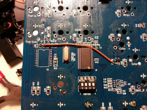
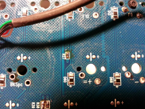
I was playing around the other night with the PCB from mine and traced the LED lines. They are structured in groups, with an empty resistor spot for each group. The other side of the resistor spots join up to a single contact. So if you solder in some LEDs, add appropriate resistors for each group and apply power to the correct point, you will have backlighting!

I also traced the WASD cluster LED contacts to an FET. There is a resistor there which acts as a current limiter for the WASD LEDs.

So, there are actually a lot of options for backlighting:

1. Add all the same LED's everywhere, bridge the resistor spots and connect the main contact point to power via an appropriate resistor for full backlighting all the same colour and brightness. [EDIT] Need to calculate resistor values per group to retain the same current for each LED.

2. Use different resistors for each group for custom brightness per group (like alpha keys, modifiers, numbers, functions, arrow cluster, etc).

3. Use different colour LED's for the groups and an appropriate resistor for each LED type (for instance white LEDs are often 3.2V, "normal" reds are 2.2V, etc.)

4. Just put LEDs on the keys you want them.

You can then either hook the main contact point to +5V for constant backlight or to the FET so they switch on with Fn+F9 :D

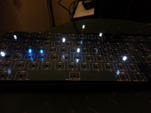
I bridged all the resistor spots, put an LED into each group to test and connected the main contact point to the same resistor that runs the WASD LEDs just to test.
39757-0

39759-1

39761-2

Have fun!

P.S. - If I find the time I will make an image of the key groups and where the resistor for that group goes. For now I was just messing around with ideas. Also note to be careful not to draw too much current, choose your LEDs and resistors appropriately.
« Last Edit: Fri, 18 October 2013, 09:15:28 by Oobly »
Buying more keycaps,
it really hacks my wallet,
but I must have them.

Offline metalliqaz

  • * Maker
  • Posts: 4951
  • Location: the Making Stuff subforum
  • Leopold fanboy
Re: Ducky G2 Pro backlight mod
« Reply #1 on: Fri, 18 October 2013, 07:18:45 »
You... bridged the resistors?

Offline Oobly

  • * Esteemed Elder
  • Thread Starter
  • Posts: 3929
  • Location: Finland
Re: Ducky G2 Pro backlight mod
« Reply #2 on: Fri, 18 October 2013, 08:21:49 »
You... bridged the resistors?

Well, I bridged the places where the resistors for each LED group should go, but ran them off the existing resistor for the WASD group. So they are all running in parallel through a single resistor.

You should use this formula for calculating the resistor value for each group of LEDs for full brightness:

Resistance = voltage drop desired across resistor / current through resistor

So,

Resistance = (Source voltage - LED voltage drop) / (Current rating of LED * number of LEDs in group)

For instance, if you have a group of 5 LED's and you're using 3.2v white LEDs with 20mA current rating:

R = (5-3.2)/(0.020*5) = 18 ohm

If you want to use 86 standard 2.2v LEDs at 20mA:

R=(5-2.2)/(0.020*86) = 1.6 ohm

Just choose the closest value of resistor you can find greater than the calculated value.

Bigger resistance will equal lower brightness.
Buying more keycaps,
it really hacks my wallet,
but I must have them.

Offline metalliqaz

  • * Maker
  • Posts: 4951
  • Location: the Making Stuff subforum
  • Leopold fanboy
Re: Ducky G2 Pro backlight mod
« Reply #3 on: Fri, 18 October 2013, 08:29:10 »
Yes I know how Ohm's law works.  Each LED should have its own load, though.

Offline Oobly

  • * Esteemed Elder
  • Thread Starter
  • Posts: 3929
  • Location: Finland
Re: Ducky G2 Pro backlight mod
« Reply #4 on: Fri, 18 October 2013, 08:47:28 »
Yes I know how Ohm's law works.  Each LED should have its own load, though.

This PCB (and AFAIK almost all keyboard PCBs) doesn't make provision for a resistor for every LED. The brightnesses may vary between LEDs in the group, but the overall current is limited and LEDs can handle the slight differences in current, especially if you go a bit higher on the resistances. There's the way it SHOULD be (resistor on every LED) and then there's the way it HAS to be given what we have (one resistor per group).

I just hooked them all up to test.
Buying more keycaps,
it really hacks my wallet,
but I must have them.