Author Topic: Gutz’s Access-IS project  (Read 2072 times)

0 Members and 1 Guest are viewing this topic.

Offline berserkfan

  • Thread Starter
  • Posts: 2135
  • Location: Not CONUS Not CONUS Not CONUS Not CONUS
  • changing diapers is more fun than model f assembly
Gutz’s Access-IS project
« on: Sun, 17 August 2014, 03:51:50 »
Inviting all geekhackers to weigh in!

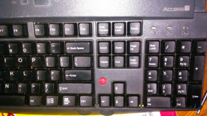
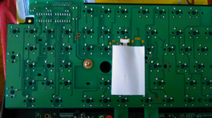
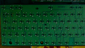
I got the following keyboard from Ebacho recently. The price was very nice, and the keyboard itself is very solid. Here it is. It is one of the heaviest Cherry MX keyboards I have ever used.
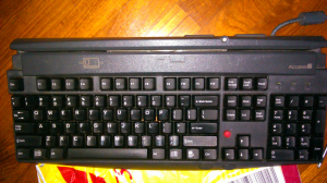
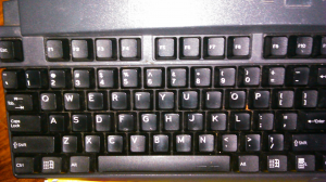
74781-074783-174785-274787-374789-474791-5

One note (absolutely not a complaint about Ebacho; I just like observing such things). Keyboard was incredibly dusty inside. Bunnylake’s entire family was living inside aka many big dust balls. Yet not a single screw was even slightly corroded. Of course, Ebacho lives in California and gets his stuff from recyclers in CA. In a humid environment like Singapore, the situation would probably be reversed. Tiny dust balls, and lots of rust.

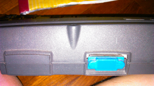
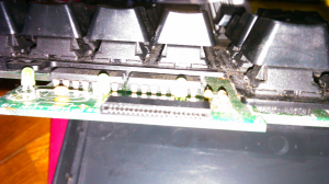
My observation about the dust bunnies is significant. This is the dustiest Cherry MX keyboard I have ever come across. (And I have bought many filthy ones from Taobao to desolder clears from!) I suspect the dust is getting in through the credit card swipe at the top. Since I don’t need to use that credit card swipe (hint, hint, guys, especially people like Fohat who have a good sense of mechanical fixes) I need to fix it such that dust doesn’t go inside the keyboard anymore.

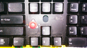
I was gratified to find that the trackpoint works well. Not so happy to find that the trackpoint has sucky switches. Of course, that’s going to change with all of your help!

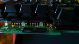
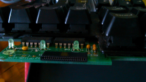
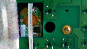
OK These are the trackpoint switches. They’re not actuating well. Time to change. But what can I change them to? (Need some names and specifications.) Also I note that the soldering is kinda odd. I can’t see the contacts. Are the contacts merely too short, and hidden inside the dual layer PCB?
74807-674809-774811-874805-9

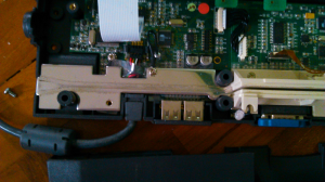
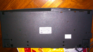
OK, and here you can see that the keyboard has what seems to be two sealed USB ports and a covered serial port at the back. Not sure what they do. I hope keyboard can be turned into a USB hub, although I really could not remove the plastic cover from the usb ports. (Hints, guys?)
74787-10


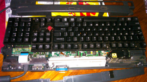
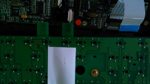
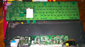
Now take a look at what I deem is the weakest link in this keyboard. The kb and trackpoint communicates with the controller only through one very flimsy cable. This one. I counted 21 contacts. Is it possible (theoretically) that if I connect these 21 contacts to a teensy++, I can have my own tiny little keyboard controller? I don’t need to go through that big controller? I am really not appreciating all the extra stuff which adds unnecessary weight and size to the keyboard. [Having read a bit I do understand that the teensy doesn’t come with mouse control, but of course again I am hoping that Soarer has been secretly working on mouse support.]
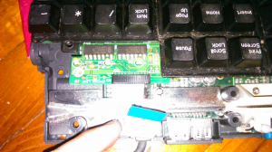
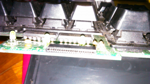
74797-1174799-1274801-1374803-14

Since I don’t have good soldering skills I am wondering how else to connect the 21 contacts to a teensy/ arduino. Really find that gigantic controller quite unnecessary.

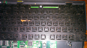
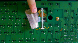
OK, here’s the PCB. I am not familiar with trackpoints, so please guide me. I understand trackpoints are hard to get, and don’t want to destroy it accidentally while desoldering the Cherry MX blacks. Does anyone have advice regarding the trackpoint?

Also note that the switches seem to be PCB-mounted with diodes, although there is a plate. I don’t have much experience, but I have never seen this kind of setup before.

OK, that’s it for now; I’ll wait for people to weigh in before deciding what to do. In general I am hoping to do a plate mod to allow switches to be changed, and I am hoping to change the return key to ISO (notice the PCB allows it). I also want to do something about the lousy trackpoint switches, as well as sealing off the keyboard at the top (remove the credit card swipe as well). I would like to liberate the two USB ports at the back and turn this into a USB hub.
74813-1574815-1674817-1774819-1874821-1974823-20

Judging from the weight I am not dealing with an aluminium plate, so I guess there’s going to be a lot of laborious cutting involved and the eventual fit won’t be good. Since it is my little finger striking the return key, I think I can afford to be ‘pcb-mounted’ there i.e. I’ll cut the plate big enough to allow the switch to be placed in the ISO position. Since my cutting won’t be exact, the switch won’t fit exactly and won’t be supported by the plate when in use.
« Last Edit: Sun, 17 August 2014, 04:07:59 by berserkfan »
Most of the modding can be done on your own once you break through the psychological barriers.

Offline dorkvader

  • Posts: 6288
  • Location: Boston area
  • all about the "hack" in "geekhack"
Re: Gutz’s Access-IS project
« Reply #1 on: Sun, 17 August 2014, 08:56:55 »
Typical access-IS quality! They make a good keyboard.

Some notes: TP appears to be just screwed into the plate. Remove the screws and unplug TP cable from KB PCB. You move the black part of the connector "down" (towards the TP buttons) and the cable just slips out (It's a ZIF cable). A bit harder to get back in. insert cable and hold it there with a finger. Use a nylon stick, tweezers, or fingernail (or pencil / pen whatever) to close the connector by sliding black part into place. You will probably have to remove the red cap off the top of the TP to get it out. Just pull straight up on it and it should come off. They are meant to be replaceable. Then take the screws out, remove TP module.

getting USB blocker off: Looks like it's slotted into the case. To remove: take the controller PCB out completely. Unscrew all the screws, looks like it lifts straight up. Then the blocker should unplug from the USB ports no problem.

I only see one picture of the front of the PCB where the TP button switches are, but you can see one trace there. Other trace appears to go to ground. You can replace them with microswitches (that cherry, omron, etc. make) and glue them to the PCB or case. Not sure if this produces the feel you like but microswitches (same as used in mouse buttons) are traditionally used in trackpoints. I prefer cherry ones to omron (sharper tactile click)

as far as dust: you're luckly you haven't got a G80-8200 from J&R: those keyboards were dusty

PCB mount switch with plate. Pinnacle and Deck both do this too, not sure why. I guess it costs the same for them and might help align the plate during soldering ...?

Enabling USB ports: The hardware appears to be present (no missing chips and suchlike near the ports) but it's hard to say: I would expect them to be disabled in firmware. You might or might not be able to enable them using Access-IS' program.

about the "odd" soldering on the TP switches: again: hard to say. The one picture isn't complete, but those two holes look like they are not being used. I would expect the switch itself to be surface mounted to the other side of the PCB. Those holes are usually for a different type of switch (like they tell the pcb designer to go ahead and make it compatible with both so they can switch components if one vendor runs out)

Easiest way to connect to teensy is to get longer a ZIF cable that'll fit in the connector on the switch PCB and then split it apart like what I did on that G80-1950. You can then solder each part to the teensy. Another way to do it is to solder to the pads on the connector. I notice it's through hole making it easier, but it's also very closely spaced. Not sure if you can solder to that or not.

modding to ISO will be "easy". You just cut a large hole in the plate around the area and PCB mount switches to the PCB. The hard part will be the stabilizer for enter. Not sure what to do with that. Right now I'm thinking get a PCB mount stab, cut the pins off the bottom so it sits flush with the PCB and then glue it down.

KB controller: I think TMK_firmware supports mouse keys? Not sure about trackpoints. TPs usually just use a dedicated PS/2 connection, so you could use two teensies. one for a KB controller and one to convert the TP module to USB. There is some good news though. See the black cable: there's actually two PCBs in there. You can almost certainly remove one completely, leaving only the (quite small) KB controller. You'll lose the serial port, mag stripe (CC reader) functionality, and whatever that black thing is on the right but it'll weigh a lot less. This is what I would do, were I you.

OK I think I answered most of the questions. Please reply with more if you have them.

Offline berserkfan

  • Thread Starter
  • Posts: 2135
  • Location: Not CONUS Not CONUS Not CONUS Not CONUS
  • changing diapers is more fun than model f assembly
Re: Gutz’s Access-IS project
« Reply #2 on: Sun, 17 August 2014, 10:59:41 »
This is another fantastic Dorkvader-style reply. Meaty like not just a plate of steak, but an entire steer.

I will need some time to absorb and carry out all suggestions.

I’m terrible at taking photos. But it seems as though the Trackpoint button switches are soldered from the top on pads (is that called SMD soldering as opposed to through hole?). So there are two holes on the PCB for the trackpoint, but these two holes don’t seem to be used and are not compatible with switches that need 3 mounts.

So how should I put in Cherry switches? Aren’t they ‘through hole’ (dunno if I am using this word correctly)? So I have to kind of put their leads into pools of solder on the pads, after which apply hot glue to hold them in place?

Actually all photos were thoroughly vacuumed already. You are not seeing any real dust. In any case I wasn’t complaining; I was treating it as a fact and information input. The scarily huge amount of dust inside is relevant because the space underneath the keys was actually much less dusty. You see, it’s much easier to vacuum the top of the keyboard, or turn it upside down periodically. The inside is hard to clean. And it’s clear that this design is very friendly to dust bunnies accumulating inside. The Cherry MX8xxxx series have better designs, less dust prone. So I must find some way to seal the keyboard and it’s obvious all the dust is going in from the credit card reader on top. Just don’t know how to do that in a professional and attractive manner.

ZIF cables: can I just buy a random one like this: http://www.ebay.co.uk/itm/Flip-Ribbon-Cable-for-ZIF-SSD-HDD-Flip-Connectors-for-Samsung-Drives-/151053430844
That has 40 pins. Presumably I tear off 19 pins and can connect the remaining 21 (assuming I hadn’t counted wrong) to a teensy? These cables look so fragile that I’m worried I’ll get too rough. And you know how suxx I am at teensy soldering…

I actually have a conversation going on in the soldering thread about soldering stations. You see, I still don’t buy (pun intended) why pros want big heavy and expensive soldering stations. OK, Margo’s explanation was good for DEsoldering. But when it comes to soldering, isn’t a fine, non clumsy tip, a thin, not bulky power cable, better? All that 90W or whatever power, it doesn’t matter. My 30W cheapo iron works fine when freshly brasso-ed and tinned, and then I can solder pretty fast also. It’s those tiny pads (eg on leds and teensies) that I have a problem with. And a powerful soldering station will absolutely not help me; it isn’t a replacement for skill or lack of skill. I even feel it is a liability if skill is low enough.

The more I look at this keyboard the less I want to mod it to ISO. It is too well built to justify my Gutzy hands sawing it apart. I think I will find another victim, some cheapo POS (and I don’t mean point of sale) keyboard. I don’t want to do what SpamRay did to his Deko. (I always rib SpamRay about it, because I find it outrageous that he took such a fantastic keyboard only for desoldering black switches and discarded the casing and PCB.)

Teensies are expensive enough; 2 teensies on one keyboard seem overkill. What about your Atmega or Arduino solutions?
Most of the modding can be done on your own once you break through the psychological barriers.

Offline dorkvader

  • Posts: 6288
  • Location: Boston area
  • all about the "hack" in "geekhack"
Re: Gutz’s Access-IS project
« Reply #3 on: Sun, 17 August 2014, 14:46:00 »
Yep, soldering on to pads on one side of the PCB is the same as SMD (SMD stands for surface mount device) It mounts to the PCB surface instead of going through the through-holes.

So I specifically meant cherry or omron microswitches. not cherry MX switches. Here's a picture

(the above appear to be fake omrons but they are microswitches!)
 I was thinking you could bend the legs over 90 degrees, solder leads to them and solder those leads to the through-holes (or pads if you have to) then position them under the tabs on the buttons and glue them in place.

Come to think of it, my two access-IS matrix keyboards (which are also built really well) were exceptionally dusty. Cherry KBs are easy to clean though, not like leaf springs or hitek / stackpole switches.

As far as dustproofing the KB, I'm still thinking on it. Right now, I'm toying with the idea of blocking the magstripe reader with a bit of cheap rubber (EPDM or the like) and maybe some glue to seal the ends.

ZIF cable: you have to be really careful. The one you linked probably won't work. #1 is that it's got too many pins (and they're really close together so it's hard to separate them properly) #2 is that the pin pitch (distance between pins) is likely wrong. It also looks like it's a cheaper one using carbon contacts in which case you can't really solder to it. I'm still not sure if this is the best way to do things. I will have to think on it. Maybe I just make a teensy - to - ZIF assembly and mail it :p

Soldering stations: Well it really depends. See, you can solder with just a cheap iron. A big expensive station makes it easier. I like temperature-sensing stations (like PACE sensatemp and OKI / Metcal smartheat). They sense the thermal load on the tip and respond accordingly. Since it's backed by 60 W - 130 W it responds really quick. This means it heats up in less than 10 seconds and also melts joints quickly (even if they are on ground plane.) But the best part about it, is also the part that makes them ideal for line soldering is that they heat up pretty much any joint in exactly the same amount of time. This means you know when the joint will melt before it does and can keep heat off it for longer. This is the part that makes it a lot easier for me, and why I recommend such systems, especially over a temperature adjustable one. Good stations usually have a lot more and better tips available. Good tips can also last a lot longer. My cheapie iron tip lasted like a year of minimal use. My "good" metcal tips have lasted several years of good use, and the temperature shock of thousands of desoldered joints. It has some oxidation away from the tinned-area, but the tinned area is thick and bright and as shiny as they day I got it.

---
I recommend a cheap arduino pro micro instead of teensy for any / all converter projects. It doesn't have enough pins for all keyboards so it's not ideal as a KB controller, but it's pretty much perfect for a protocol converter. I'm using one in my WY-30, another for PS/2 & AT to USB, etc. They are like $5 to $7 and awesome.

I think I'm the only one that appreciates that pinnacle DEKO keyboard. Everyone else I've talked to that had one desoldered the switches and pitched the rest.

Offline berserkfan

  • Thread Starter
  • Posts: 2135
  • Location: Not CONUS Not CONUS Not CONUS Not CONUS
  • changing diapers is more fun than model f assembly
Re: Gutz’s Access-IS project
« Reply #4 on: Sun, 17 August 2014, 16:28:02 »
Yup, I did mean the microswitches (just didn't know the correct words). I recycled mine from various G80-8113s. Always figured the microswitches could come in useful someday.

Definitely this project I can't do in the next week. The Cherry microswitches have different dimensions from the original microswitches so the mechanical process of actuation will have to be thought over.

Access-IS seems to employ a different way of incorporating the card reader. So the opening easily feeds into the rest of the keyboard allowing more dust in.

ZIF cable: So there are different specs, and that they are not like Dupont connector cables with standard dimensions? I'll have to research this also. So many things to do!

I'm beginning to see how a pro would like things like the sensatemp and the smartheat. I don't need these and will never though. EG my 30W needs at least 5 minutes to heat up, but that doesn't bother me because I'm always doing other things in the meantime.

For melting joints, I basically see and feel for myself. When a solder joint gets soft and when moving the tip causes the entire joint to move, it's all liquid and can be sucked up. This unprofessional approach is bad when it comes to tiny joints like LEDs, since it is hard to see or feel that the solder has all melted. So a sensatemp user has a huge advantage there.

Yes, one thing I feel strongly about, is that cheapo tips don't come with replacements. You just buy a new soldering iron and throw the old one away. But maybe there are replacements - I just need to look harder on Taobao.

Ha, you are not the only one who appreciates the Deko. Why else would I have sent it to you? I actually asked SpamRay for the pieces at first, but turns out he'd discarded the pieces. I think I might actually look for another Deko just so that I could mess with it myself. Between you and me, I'll probably wind up with at least one working Deko no matter what disasters I bring down on one Deko.

Sooner or later I will look for arduino pro micro on Taobao. For now I've again overspent and won't be buying from Taobao for a few months. Sounds familiar? But yeah, I think it's silly to use only 4 pads on the Teensy to convert stuff. If 4 pads are all that are needed then maybe a smaller chip with as little as 4 pads would work as well?
Most of the modding can be done on your own once you break through the psychological barriers.

Offline berserkfan

  • Thread Starter
  • Posts: 2135
  • Location: Not CONUS Not CONUS Not CONUS Not CONUS
  • changing diapers is more fun than model f assembly
Re: Gutz’s Access-IS project
« Reply #5 on: Wed, 20 August 2014, 01:34:02 »
Update on my Access IS project.

The Access-IS keyboard is exceptionally hard to desolder. I have desoldered a few double sided PCBs by now, but this is extra hard because of two factors:
1)   Diodes. Soldapullt seems useless on them, so liberal use of wick thus incurring even more expenses. Diodes double the number of contacts I’m forced to desolder, and these are harder than regular switch contacts, so it is very irritating.
2)   The plate design. Access built its plate with tighter tolerances than other keyboard manufacturers, so each switch fits very tightly in its hole. Even though during desoldering I grab each individual pin with tweezers to confirm that the pin is free, the switch is still very hard to remove. A high degree of brute force is needed because they are that tight. I can assure all readers that I have already verified repeatedly that all pins are free so I am not ripping up solder joints.

Based on the pain factor from desoldering, I am now much less enthusiastic about modding Access’ keyboard. Furthermore since there is some rust, I need to paint this plate. And because plate is already so tight, I’m not that keen to put 1 primer and 1 paint coat on it. I might put this project aside for the time being; it’s not that rewarding now.

I am actually considering turning this plate mounted keyboard into a PCB mounted one, if only because I don’t even want to desolder it ever again in future. But of course it makes a mockery of Access’ quality build, sigh. Even now, barely 1/6 of all keys have been desoldered. That’s how bad it was.
Most of the modding can be done on your own once you break through the psychological barriers.

Offline damorgue

  • Posts: 1176
  • Location: Sweden
    • Personal portfolio
Re: Gutz’s Access-IS project
« Reply #6 on: Wed, 20 August 2014, 08:42:10 »
So I specifically meant cherry or omron microswitches. not cherry MX switches. Here's a picture
Show Image

(the above appear to be fake omrons but they are microswitches!)
 I was thinking you could bend the legs over 90 degrees, solder leads to them and solder those leads to the through-holes (or pads if you have to) then position them under the tabs on the buttons and glue them in place.

There are micro switches with already bent leads. See attached spec sheets.

Offline berserkfan

  • Thread Starter
  • Posts: 2135
  • Location: Not CONUS Not CONUS Not CONUS Not CONUS
  • changing diapers is more fun than model f assembly
Re: Gutz’s Access-IS project
« Reply #7 on: Mon, 01 September 2014, 16:19:31 »
I have run into a couple of problems with my Access-IS keyboard also. 1) I lifted two traces while desoldering and have no idea how to put the copper back. 2) I have no idea how to separate the trackpoint assembly. The cables aren’t that easy to pull and I decided against using too much force before consulting Geekworld.
Most of the modding can be done on your own once you break through the psychological barriers.

Offline dorkvader

  • Posts: 6288
  • Location: Boston area
  • all about the "hack" in "geekhack"
Re: Gutz’s Access-IS project
« Reply #8 on: Mon, 01 September 2014, 18:00:11 »
I know exactly how to get that TP module out.

That type of cable and those ZIF connectors are very very common in laptops.

What you have to do is "pull" the brown bit forward, about 1mm or so. It'll click out of place and become loose. At that point you can remove the cable: it takes almost no force to do so.

To remove the cable from teh TP module end, instead of pulling the brown bit forward, rotate it up with a fingernail, nylon stick (spudger) or flatheat screwdriver. Then pull the cable out.

Once the cable is out, unscrew the three screws (look like Phillips P0 or maybe P1), remove the rubber cap, and it shoudl fall out into your hand.

Putting the cable back in can be a little more tricky, but even if it's not fully seated, it'll usually still work. Re-seat it of course if it doesn't.

As to the lifted traces. You can sometimes just tape them back down to the PCB, but at that point I prefer to replace the trace completely with a jumper. Solder a bit of wire from the switch pin to a via or another switch, thereby "replacing" the trace completely with a bit of wire. Tape or glue the wire to the PCB.

Oh, as an aside, Those cable are pretty hardy. Even if you pulled it out of the connector without releasing the catch, it'd probably be just fine. Newer technicains do that all the time with the trackpad cables on laptops and they're fine. You have to release the catch properly to put the cable back in though.