SOLVED! Thanks to those who helped out. Turned out to be a short from an LED pin to an unused pad from some leftover solder residue.
Hey everyone!
So I've been working on building my very first custom keyboard over the past few days, including lubing and modding switches/stabs. I'm building a Tofu60 with a DZ60 and Gateron Black Inks, lubed with Trib 3204. I put together the board the other night and had everything soldered and all of the switches were working properly. But I put in a few keycaps and noticed that the spacebar felt mushy. After taking the board out of the case I noticed the stab wire had fallen out.. no problem, I'll just have to desolder a few switches and get it back in place with tweezers. Which I was able to do.
However, in the process I must have broken a trace or lifted a pad because after putting the switches back in I realized that an entire column of the pcb has stopped working. Now.. I'm still really new to all of this so I'm learning as I go but I've done some testing and need some help to move forward.
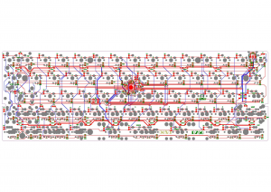
So, the switches I desoldered to fix the stab were the spacebar "c" "v" "b" "n" "m" and ",". After soldering the switches back on and testing them, an entire column wasn't working. This column is made up of the following keys; "6" "t" "g" "b" and spacebar. You can see in the DZ60 circuit diagram below that those keys are all in the same column in the keyboard matrix. So it makes sense that they could all break at once.

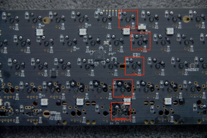
Next I wanted to find out what exactly isn't working for each switch, and if I could just create bridges to nearby switches in order to make it work. First I'll fill you in on how the pcb is laid out. In the image below I have labeled which switches are the ones that aren't working. As well as their pins; the pins labeled A are the vertical pins responsible for calling which column is being triggered. The pins labeled B are the horizontal pins responsible for triggering a particular row on the keyboard.


Through my testing of the pins by shorting them with other pins on the board, I found a few things.
1) All of the
B pins are completely functional and can be used with all of the other A pins on the board (other than the A pins in this column)
2) All of the
A pins don't seem to be sending any signal at all EXCEPT for the spacebar (read the next point for more about the spacebar)
3) The spacebars
A pin has a strange behaviour when shorted with another columns' A pin. It will trigger that
entire column at once. None of the other keys on the keyboard seem to have this behaviour.
So that's it.. I'm not sure how much info this gives you to help me figure this out.. but I'd love any ideas or suggestions. I'd like to note that this ENTIRE column isn't working. This includes the other set of pads directly next to the current spacebar and "b" positions.
I think the issue is with the spacebar or a trace near it since that is the only key to have any effect from it's
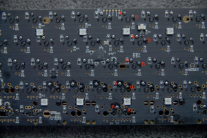
A pin and it has that strange behaviour. I'll leave you with an image of the entire board and non marked-up photos of the areas of interest. I appreciate any help with this, as I'd love to be able to make my first keyboard work.
Thanks!