Author Topic: Designing a completely new switch.  (Read 4297 times)

0 Members and 1 Guest are viewing this topic.

Offline mustcode

  • Thread Starter
  • Posts: 158
Designing a completely new switch.
« on: Wed, 07 March 2018, 14:06:29 »
Hello!

To be completely honest, I don't have a convincing reason as to why I'm trying to design a new switch... and I'm not gonna try to come up with one, because this project actually started from me losing a lot of sleep nights after nights as I couldn't stop thinking about this switch idea, and I know myself well enough to realize that I need to do something about it before I turn insomniac   ^-^

But I can tell you why I think this design is interesting, and I'll let you guys decide if it could be beneficial to the community!  :D

DISCLAIMER: I'm not a professional designer by any standard, I'm just a game programmer who knows a little bit of Sketchups (pretty useful for making placeholders). So, please don't expect professional quality CAD files from me :-[ However, I did quite a few 3d printing to verify that the general design will 'most likely' work (definitely didn't work the first couple of time, this is actually ver.11  :rolleyes: )

First let's look at what it looks like:
190835-0
This image shows how it looks in general and 2 slider variations. I'm not sure which one will feel better or smoother, but I know that artisans with THICC stem will not fit the walled version, and the walled version may provide extra stability with SA caps. The main housing is 14mm x 14mm x 14mm and the total travel is 4mm. It is designed from to ground up for enthusiasts, meaning, I'm not trying to design the 'best' switch in any category in particular, but I want it to feel great, easy to customize and create variations, a joy to work with, and allows for simple and high quality keyboard designs. It is not MX compatible except for the keycap mount and spring. I tried making it completely MX compatible at first, but in the end it greatly limits what I originally wanted to create, and I don't even know if this thing will go anywhere more than a few 3d printed fidget toys sitting on my desk, so why not try going all-out crazy first  :cool:

Here is the exploded view:
190837-1
190839-2
190841-3
The spring and contact are not shown here, just the slider and housing. I've designed it so that any MX spring will fit, and you can probably see where the spring will be, so I didn't bother drawing it. As for the contact, there are plenty of space in the housing, so there are many options, we'll get to that later.

At this point you might be wondering about the cross-shaped piece that hold the spring. There are reasons why it look like that: First, it allows for an easy way to open and close the switch without any tools while still securely holds everything in by clipping to the main housing with the notches on all 4 sides. Second, the cross act as mounting, holding the switch to the pcb without any tilt. Third, dust can be blown out of the switch without disassembly. And finally, light can shine through the switch directly from bottom-center (we'll see where to put the LED in a bit).

This view from the bottom gives a better view of how the housing, slider and the cross fits together and a better view of how the slider is held inside the housing:
190843-4
Here you can see the grooves on all 4 sides that are keeping the slider as vertical as possible while sliding. You can see 2 of the 4 grooves extends all the way down to the bottom. The longer grooves are what mainly keep the slider on its axis, pretty common stuff, many switch have something like this. The shorter grooves are there meant to provide additional stability while still give enough room to add the mechanism for contact and tactility.

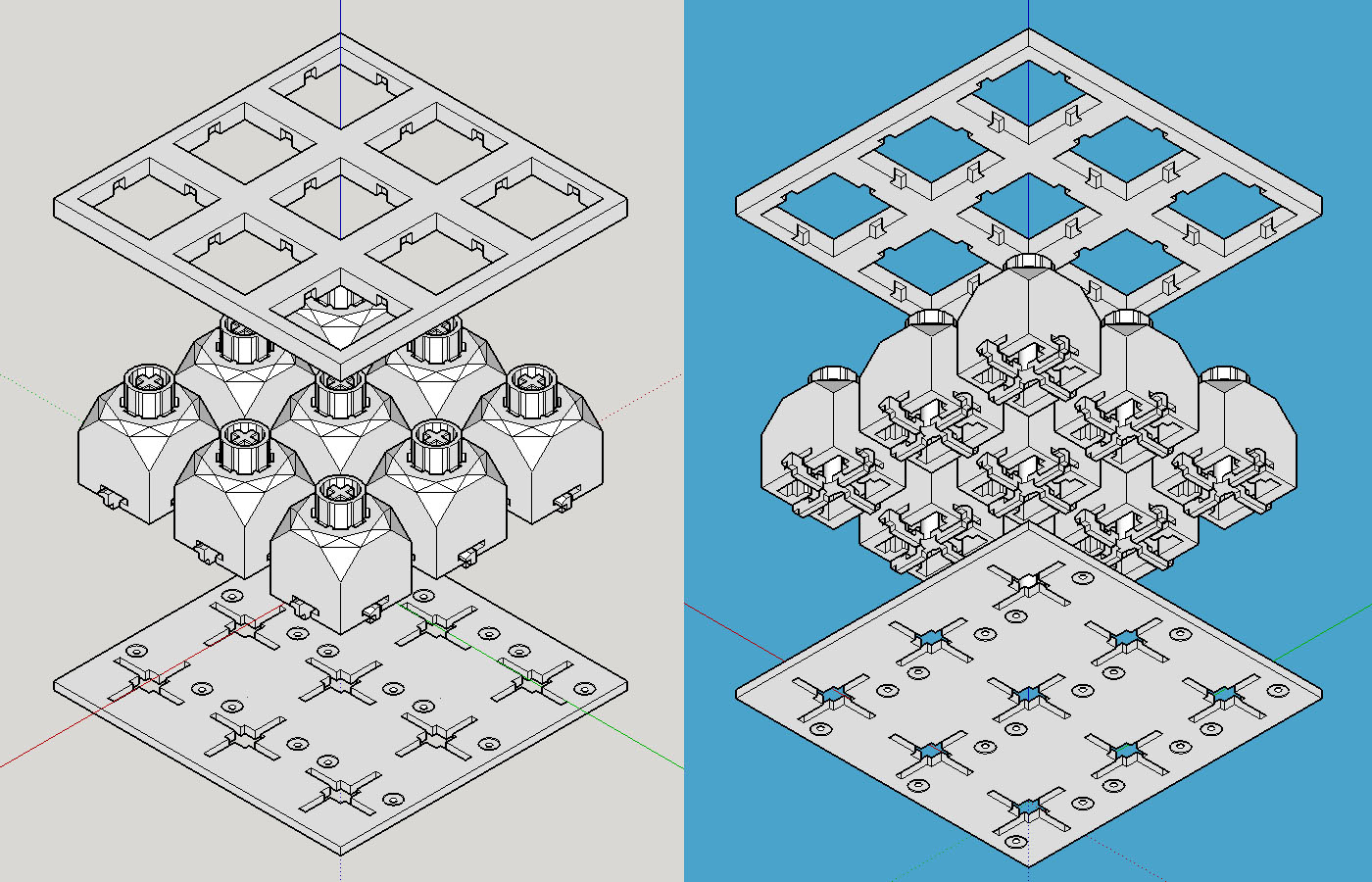
Here is how the switches are installed on the pcb and how they are held in place:
190845-5
190847-6
190849-7
The bottom rectangle that the switch sits on is the pcb, here you can see how the cross piece mount onto the pcb and how it can keep the switch from tilting. The top rectangle is what I call the 'retainer'. It is meant to sandwich with the pcb by screws and keep the switches in place by holding on to the notches on all 4 sides of each switch. The retainer is not meant to be the 'plate' or part of the case, it should be inside the case and made of non-conductive material. Solder is not needed as the switch should make a firm contact to the pcb from the sandwiching of the retainer and the pcb.
If this design works out, assembling switches to the pcb will be very simple, add switches, screw in the retainer, done.

Here you can also see the how the holes on the pcb can allow LED to be placed on the bottom side of the PCB, and still shine through the bottom-center of the switch, allowing the same LED to be used for both under-glow and switch backlit. You can even use separate led strips for each row instead of soldering all LEDs to the pcb.

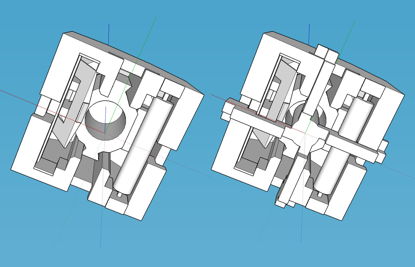
Now let's talk contact, here is where I get a little crazy... But first, let me say that I intentionally design the switch so that it has plenty of room for contact mechanism, not nailing down the contact for this switch. But because the contact is kind of important for a switch, and a switch is not a switch without the contact, so I still want to give my idea of the contact that I would like to see the most  :D
190851-8
190853-9
Sorry, it is kinda hard to find an angle that can explain it visually. But for those who can make out what it is... Yes! It is a reed switch! The tube in the picture is a reed switch, the rectangle block above it is a magnet, and on the opposite side is a click-leaf similar the ones in the beloved Alps switches. The size of the reed switch tube is 10mm, although not the most commonly available types, I was able to find several suppliers through a quick search, so at least it's out there. If the reed switch idea turns out to be a bad idea due to cost, availability, or other reasons, the space could fit anything from: a magnet for hall-effect switch, an Alps-style switch plate, an optical switch sensor, etc.

And that's it for now! Thank you for your time going through the long post, I'm always looking for feedback to improve on this design so feel free to let me know how stupid I am :)) And finally here's a GitHub link to the source file for the switch for those who want to take a closer look at the 3d file:

https://github.com/mustcode/switch


Offline funderburker

  • * Exquisite Elder
  • Posts: 1396
  • Location: Latvia, Riga
Re: Designing a completely new switch.
« Reply #1 on: Wed, 07 March 2018, 14:37:58 »
First of all - SICK!  :thumb:

Secondly - I read most of the paragraphs but skimmed over some stuff as it's late and I don't have the time to discuss stuff more thorough BUT idea and the design looks interesting and I like the customizability aspect for the stem. Also the retainer thingy is quite an interesting idea and sounds cool as hell.

So I'll be back here and try and find the time to add to this discussion. Keep it up, man!  :)
Keyboard design by Skepur

My boards: TMO50 FE:06 | LAGOM Groda-T | TMOv2 R1 prototype | Onyx FRL TKL prototype | Stege TKL prototype | Ellipse prototype | Cyberstar

Offline senso

  • Posts: 47
  • Location: Portugal
Re: Designing a completely new switch.
« Reply #2 on: Wed, 07 March 2018, 14:48:39 »
Interesting, but that is a lot of tiny features, manufacturing the injections moulds to get that right wont be cheap :(

And even then, looks like it needs better tolerances than what the typical switch designs demand.

Offline mustcode

  • Thread Starter
  • Posts: 158
Re: Designing a completely new switch.
« Reply #3 on: Wed, 07 March 2018, 15:19:40 »
Interesting, but that is a lot of tiny features, manufacturing the injections moulds to get that right wont be cheap :(

And even then, looks like it needs better tolerances than what the typical switch designs demand.
Oh, interesting. I had some success with 3d printed prototypes, but I was not aware that this is conidered complex for real production. As mention above, I'm a programmer by profession and have zero experience with manufacturing something like this. If you can give some more details on what part of the design is iffy for real manufacturing, that'll be awesome because those are exactly the kinds of details that I will need to know if I want to push this further.

Offline mustcode

  • Thread Starter
  • Posts: 158
Re: Designing a completely new switch.
« Reply #4 on: Wed, 07 March 2018, 15:23:39 »
First of all - SICK!  :thumb:

Secondly - I read most of the paragraphs but skimmed over some stuff as it's late and I don't have the time to discuss stuff more thorough BUT idea and the design looks interesting and I like the customizability aspect for the stem. Also the retainer thingy is quite an interesting idea and sounds cool as hell.

So I'll be back here and try and find the time to add to this discussion. Keep it up, man!  :)
Thanks man! I'll be looking forward to hear more from you :)

Offline MatchstickMan

  • Posts: 131
  • Location: Seattle
  • CAD Jockey - YOLO Enthusiast
Re: Designing a completely new switch.
« Reply #5 on: Wed, 07 March 2018, 16:50:09 »
This looks great! I will always second a Hall Effect sensor for a switch, but optical may be the game to get into right now. Especially if you can make it analog-like to detect the distance pressed, there's a lot of interest in that idea from a gaming perspective.

As for CAD, I'd be happy to help out if you need any assistance/advice (I mostly do cadstuff as a job and when I'm at home). Fusion 360 has a "Startup" version that you can use for free that's a pretty solid parametric CAD package, especially compared to Sketchup.
Current Projects:
- SouthPad -- Left-handed Numpad
- Full Split (Currently on hold)

Offline mustcode

  • Thread Starter
  • Posts: 158
Re: Designing a completely new switch.
« Reply #6 on: Thu, 08 March 2018, 01:28:03 »
This looks great! I will always second a Hall Effect sensor for a switch, but optical may be the game to get into right now. Especially if you can make it analog-like to detect the distance pressed, there's a lot of interest in that idea from a gaming perspective.

As for CAD, I'd be happy to help out if you need any assistance/advice (I mostly do cadstuff as a job and when I'm at home). Fusion 360 has a "Startup" version that you can use for free that's a pretty solid parametric CAD package, especially compared to Sketchup.
Thanks for the CAD advice :) I'll definitely take you up on that if this ever going to production.
About the contact mechanism, seemed like there's a lot of love for hall-effect, so I'll definitely keep that in mind.

Offline mustcode

  • Thread Starter
  • Posts: 158
Re: Designing a completely new switch.
« Reply #7 on: Wed, 11 April 2018, 11:05:29 »
A quick update for those of you who are interested in the progress :)
I found a place on 3dhubs with pretty good printers so I was able to test the current design a bit more. I printed this prototype with EnvisionTec RC31 with 32nm layers, and result is not bad at all. The switch works properly in general, however, smoothness was not as good as I'd hope (considering the high quality of the print) so I wanted to make some more adjustments to reduce friction while trying to maintain stability.
Sorry to those of who are interested in the project as I'm taking this way slow... Each round of prototype is not cheap and takes quite a long time, so I need to make sure to think things through and don't make stupid mistakes, which cost a lot of time and money

Offline MatchstickMan

  • Posts: 131
  • Location: Seattle
  • CAD Jockey - YOLO Enthusiast
Re: Designing a completely new switch.
« Reply #8 on: Wed, 11 April 2018, 12:03:58 »
Good stuff! Whip out the sandpaper and get to smoothing out some of those riding surfaces yourself. Some fine grit paper ought to make that pretty close to production quality if you're careful enough. Then you can see what adjustments need to be made.

Be cognizant of where injection molded split lines could/should be. This could help you out immensely later on.

Great work! I'm excited to see where this goes!
Current Projects:
- SouthPad -- Left-handed Numpad
- Full Split (Currently on hold)

Offline BlindAssassin111

  • Posts: 1107
  • Location: Behind you
  • I design keyboards and stuff.
    • Viktus
Re: Designing a completely new switch.
« Reply #9 on: Wed, 11 April 2018, 12:16:10 »
Just wanted to jump in and say that your parts are actually not possible to injection mold due to internal overhangs. So you would have to redesign in order to actually achieve a production ready switch. I like that you are trying to innovate, not trying to knock you down, just wanted to let you know.

Main issue is you have to be able to insert a metal insert into the injection mold cavity to produce the internal geometry, so anything that prevents the insert from going in and out once the plastic is injected, it  would be impossible to make. You have to think about it in a different manner than just design, you need to start thinking of designing for manufacturability next, as 3D printing is not a viable solution due to cost unless you love paying $$ per switch.

If you want more info or anything hit me up, I am a mechanical engineer and I am currently doing injection molded parts for switches(nexus alps sliders) so I can help you understand what is possible, and what changes would allow this to actually kick off.

Offline mustcode

  • Thread Starter
  • Posts: 158
Re: Designing a completely new switch.
« Reply #10 on: Wed, 11 April 2018, 16:56:59 »
Just wanted to jump in and say that your parts are actually not possible to injection mold due to internal overhangs. So you would have to redesign in order to actually achieve a production ready switch. I like that you are trying to innovate, not trying to knock you down, just wanted to let you know.

Main issue is you have to be able to insert a metal insert into the injection mold cavity to produce the internal geometry, so anything that prevents the insert from going in and out once the plastic is injected, it  would be impossible to make. You have to think about it in a different manner than just design, you need to start thinking of designing for manufacturability next, as 3D printing is not a viable solution due to cost unless you love paying $$ per switch.

If you want more info or anything hit me up, I am a mechanical engineer and I am currently doing injection molded parts for switches(nexus alps sliders) so I can help you understand what is possible, and what changes would allow this to actually kick off.
Thank you so much for pointing out the flaw! I have never considered limitations like overhangs can prevent the part from being removed from the mold, which is an eye opener for me (and you've probably justed saved me from several rounds of prototyping). I'll start working on the redesign, so yes, if you could help me out a little more, I'd like to understand more about the manufacturing limitations of injection molding, I'd be very grateful. And good luck on the Nexus sliders, it is a great project that could have a real impact on the community!

Offline BlindAssassin111

  • Posts: 1107
  • Location: Behind you
  • I design keyboards and stuff.
    • Viktus
Re: Designing a completely new switch.
« Reply #11 on: Wed, 11 April 2018, 18:29:46 »
Thank you so much for pointing out the flaw! I have never considered limitations like overhangs can prevent the part from being removed from the mold, which is an eye opener for me (and you've probably justed saved me from several rounds of prototyping). I'll start working on the redesign, so yes, if you could help me out a little more, I'd like to understand more about the manufacturing limitations of injection molding, I'd be very grateful. And good luck on the Nexus sliders, it is a great project that could have a real impact on the community!

So the main things you need to keep in mind is:
1) How can you split the part into two halves. Almost all injection molds are split in two with inserts to form cavities, like the inside of the top housing. So you need to look and see if it is possible to split in two without something on the side preventing the part from being ejected after molding.

2) How are the cavities going to be formed. Generally you just have an insert machined that matches the cavity geometry and that allows the part to mold around it. You have to make sure, like I said before, that it is possible to insert and remove it without the part getting stuck on there due to an over hang. Also make sure that you don't have a cavity that is not in line of sight to the face that the insert is going to be placed into. Meaning if you are looking directly at the bottom face of the top housing, make sure there are no cavities that you can't see all side of, so no hidden pockets inside the part.

3) This is where it starts to get tricky. You need to plan on using what is called Draft angles. This is explained pretty well here:
Plus you get to listen to him speak, which is soothing. This is done to make it possible to get out of the mold, generally for how accurate the part geometries need to be for switches, use a draft angle of 1 degree. You need to draft on either side of the parting line(the intersection between the two mold halves) and because of this you need to check how things fit after adding the draft angle to make sure that your switch will still operate how you want.

4) Design for a standard tolerance of ±0.05mm(0.002in) as that is the norm, otherwise you pay a bit more money to get better tolerance, which is fine if you are willing to pay for it. So make sure that your geometry can support that increase or decrease in size on both parts. Meaning if the top housing dimensions on the inside are smaller, and the slider is larger, will they work fine together? Also try and keep the smallest detail above 0.3mm, this is the lower limit for most companies, and higher detail = more money.

5) Material choice is very, very important and can greatly affect how the parts feel and last. Best bet for switches is POM(Acetal or Delrin) as it is low friction and used in almost all current switches produced. ABS and PC are also common but have different properties that you need to become familiar with.

6) Under cuts are expensive, so avoid them if possible(you use them on the side of the top housing to hold the spring post in) Reason being you have to use another insert for each one of those, and each one costs money. If you have to have them just plan around that. You need to think how this part will be split up as that saves you time and headaches later on.

7) Molds cost a lot of money, for what you are doing expect ~$20k total for the top housing, slider, and spring post. The mold for my slider is ~$6k, and it doesn't look that complicated, but it has fine geometry, and the top housing is more because of the much more complicated internal geometry. Cost per part is something to keep in mind as well, don't look at $20k are shy away, if you think about how many switches you could make (500k+) the cost per switch is only $0.04, and then you pay to have each part made, which depends on quantity and can range from $0.10 for 20k parts, or much lower for higher. Plus the potential profit after the original molds are paid for, is multiple times the initial investment and that makes the project worth it if you can bring it to that point.

Probably forgetting something here, but this will lead you in the right direction and allow you to have a successful project. Hope you can make this a reality, and even if you don't you can use the knowledge learned from doing this and try and make a product that is amazing, and better because of this. If you ever need something PM me, always willing to help, and on here almost all day so don't hesitate.

Offline Leslieann

  • * Elevated Elder
  • Posts: 4518
Re: Designing a completely new switch.
« Reply #12 on: Wed, 11 April 2018, 19:10:16 »
So the main things you need to keep in mind is:
1) How can you split the part into two halves. Almost all injection molds are split in two with inserts to form cavities, like the inside of the top housing. So you need to look and see if it is possible to split in two without something on the side preventing the part from being ejected after molding.

Elaborating a bit more on this...
The plunger in the first post even without internal overhangs is at minimum a 4 piece mold. Last time we got a mold priced it worked out to about $800 (China) - $2k (US) per piece depending on where you got the mold made. Mold making is a very specific talent, just because you can machine does not mean you can make a mold and post machining prep is also far more intense than normal. Once you have a mold you can find a injection moulder and crank out parts for pennies, it's getting there that is expensive.

Injection molds for mass production typically want 1 degree tapers on everything for ease of release. The more fickle to get your part out of the mold the slower the process, the more money per item. When you are talking thousands of pieces per hour, even one second longer per part makes a huge difference in the amount you can turn out and therefore increased cost.

Also more complex and smaller the part the more pressure you will likely need, this means a more expensive injection machine. So does more mold parts. More pressure means tooling will wear faster so it means harder materials or more molds.


China
China is cheap, but if you have never done business there, I would seriously reconsider doing so or at least get referrals from people who have had work done over there. Besides taking the money and running (a common problem), quality control is often severely lacking, and then there is costs to ship back and forth for revisions.
Novelkeys NK65AE w/62g Zilents/39g springs
More
62g Zilents/lubed/Novelkeys 39g springs, HK Gaming Thick PBT caps, Netdot Gen10 magnetic cable, pic
| Filco MJ2 L.E. Vortex Case, Jailhouse Blues, heavily customized
More
Vortex case squared up/blasted finish removed/custom feet/paint/winkey blockoff plate, HID Liberator, stainless steel universal plate, 3d printed adapters, Type C, Netdot Gen10 magnetic cable, foam sound dampened, HK Gaming Thick PBT caps (o-ringed), Cherry Jailhouse Blues w/lubed/clipped Cherry light springs, 40g actuation
| GMMK TKL
More
w/ Kailh Purple Pros/lubed/Novelkeys 39g springs, HK Gaming Thick PBT caps, Netdot Gen10 Magnetic cable
| PF65 3d printed 65% w/LCD and hot swap
More
Box Jades, Interchangeable trim, mini lcd, QMK, underglow, HK Gaming Thick PBT caps, O-rings, Netdot Gen10 magnetic cable, in progress link
| Magicforce 68
More
MF68 pcb, Outemu Blues, in progress
| YMDK75 Jail Housed Gateron Blues
More
J-spacers, YMDK Thick PBT, O-rings, SIP sockets
| KBT Race S L.E.
More
Ergo Clears, custom WASD caps
| Das Pro
More
Costar model with browns
| GH60
More
Cherry Blacks, custom 3d printed case
| Logitech Illumininated | IBM Model M (x2)
Definitive Omron Guide. | 3d printed Keyboard FAQ/Discussion

Offline Jacob4341

  • Posts: 69
Re: Designing a completely new switch.
« Reply #13 on: Wed, 11 April 2018, 19:30:28 »
This is project is over my head but I do know that I for sure support new ideas and I think this one is great. I hope you continue developing this and am eager to see the next design revision that hopefully takes into account the manufacturing limitations.

The customization route that you're going with for this switch is super cool. I like the latch mechanism too. Keep it up.

Offline mustcode

  • Thread Starter
  • Posts: 158
Re: Designing a completely new switch.
« Reply #14 on: Thu, 12 April 2018, 02:22:06 »
Thank you all for pointing me in the right direction. I think I have a much better idea of the design limitations, and I'll doing some more research to make sure that the next iteration will be a lot more feasible. Will keep you guys updated on the changes!

Offline Blaise170

  • * Esteemed Elder
  • Posts: 1332
  • Location: Boston, MA
  • ALPS キーボード
    • XYZ
Re: Designing a completely new switch.
« Reply #15 on: Thu, 12 April 2018, 09:33:31 »
Looking good. It will be interesting to see the finished product!  :thumb:
I proxy anything including keyboards (キーボード / 鍵盤), from both Japan (日本) and China (中國). For more information, you may visit my dedicated webpage here: https://www.keyboards.es/proxying.html

View my current and past keyboards here: https://deskthority.net/wiki/User:Blaise170

Offline Leslieann

  • * Elevated Elder
  • Posts: 4518
Re: Designing a completely new switch.
« Reply #16 on: Thu, 12 April 2018, 20:06:05 »
Thank you all for pointing me in the right direction. I think I have a much better idea of the design limitations, and I'll doing some more research to make sure that the next iteration will be a lot more feasible. Will keep you guys updated on the changes!
You're welcome.

Every form of manufacturing has limitations as does materials, one of the things my company dabbled in was helping people go from idea to production, but it's not easy to make it profitable. Lots of people have great ideas, but can't afford or won't pay for someone to lead or help them while refusing to do the necessary homework to accomplish it on their own, as a result their products end up failing. Kind of sad as we saw some really neat ideas that will probably never get beyond the first prototype/concept stage. You already surpassed a lot of what we saw, so congrats!


I will tell you the same as we told our clients, keep doing exactly what you are doing, do as much as you can by yourself, go slow and get input and most of all ignore the big picture money. Obviously at some point large amounts of money will need to be dropped but there are ways to deal with that when you get there. For now, your energy is better spent getting a working product and then lots of testing.*

By the way, not sure what you spent on the prototypes, but often by the time you hit the 3rd prototype, you could have bought a 3d printer to do it yourself. In this case you would want a resin printer. I would look into the Maoi or a used Form Labs (preferred) and skip the cheaper Chinese clone that is out, it can work, but you lack the experience necessary to get the most from it. The downside is that resin is VERY messy, a bit toxic, and expensive, and 3d printers in general can be fickle b*tches (they themselves can be a hobby, resin is a bit less so), but it could save you a lot of money in the long run if you are willing.

*Making a rig to test presses and lifespan is easy and pretty cheap.
Novelkeys NK65AE w/62g Zilents/39g springs
More
62g Zilents/lubed/Novelkeys 39g springs, HK Gaming Thick PBT caps, Netdot Gen10 magnetic cable, pic
| Filco MJ2 L.E. Vortex Case, Jailhouse Blues, heavily customized
More
Vortex case squared up/blasted finish removed/custom feet/paint/winkey blockoff plate, HID Liberator, stainless steel universal plate, 3d printed adapters, Type C, Netdot Gen10 magnetic cable, foam sound dampened, HK Gaming Thick PBT caps (o-ringed), Cherry Jailhouse Blues w/lubed/clipped Cherry light springs, 40g actuation
| GMMK TKL
More
w/ Kailh Purple Pros/lubed/Novelkeys 39g springs, HK Gaming Thick PBT caps, Netdot Gen10 Magnetic cable
| PF65 3d printed 65% w/LCD and hot swap
More
Box Jades, Interchangeable trim, mini lcd, QMK, underglow, HK Gaming Thick PBT caps, O-rings, Netdot Gen10 magnetic cable, in progress link
| Magicforce 68
More
MF68 pcb, Outemu Blues, in progress
| YMDK75 Jail Housed Gateron Blues
More
J-spacers, YMDK Thick PBT, O-rings, SIP sockets
| KBT Race S L.E.
More
Ergo Clears, custom WASD caps
| Das Pro
More
Costar model with browns
| GH60
More
Cherry Blacks, custom 3d printed case
| Logitech Illumininated | IBM Model M (x2)
Definitive Omron Guide. | 3d printed Keyboard FAQ/Discussion

Offline tex_live_utility

  • Posts: 990
  • MX brown apologist
    • twitch.tv/salt_rock_lamp
Re: Designing a completely new switch.
« Reply #17 on: Fri, 13 April 2018, 17:01:39 »
This is really thoughtful work. One thing about reed switches (which I'm sure you know) is that they can be quite fragile.

It looks like you could actually mount a fairly traditional MX or even Alps style contact mechanism in there. You could also go with Hall effect sensors, provided you're willing to write your own firmware.
Discord: salt rock lamp#0679 | Reddit: /u/nerdponx | Deskthority: autoload -Uz | Keebtalk: salt_rock_lamp
Twitch: salt_rock_lamp | YouTube: https://www.youtube.com/channel/UCd7YXZjilUutJ6ShZWrvQtg | Instagram: @salt_rock_keyboards


Offline mustcode

  • Thread Starter
  • Posts: 158
Re: Designing a completely new switch.
« Reply #18 on: Sat, 14 April 2018, 05:28:07 »
You're welcome.

Every form of manufacturing has limitations as does materials, one of the things my company dabbled in was helping people go from idea to production, but it's not easy to make it profitable. Lots of people have great ideas, but can't afford or won't pay for someone to lead or help them while refusing to do the necessary homework to accomplish it on their own, as a result their products end up failing. Kind of sad as we saw some really neat ideas that will probably never get beyond the first prototype/concept stage. You already surpassed a lot of what we saw, so congrats!


I will tell you the same as we told our clients, keep doing exactly what you are doing, do as much as you can by yourself, go slow and get input and most of all ignore the big picture money. Obviously at some point large amounts of money will need to be dropped but there are ways to deal with that when you get there. For now, your energy is better spent getting a working product and then lots of testing.*

By the way, not sure what you spent on the prototypes, but often by the time you hit the 3rd prototype, you could have bought a 3d printer to do it yourself. In this case you would want a resin printer. I would look into the Maoi or a used Form Labs (preferred) and skip the cheaper Chinese clone that is out, it can work, but you lack the experience necessary to get the most from it. The downside is that resin is VERY messy, a bit toxic, and expensive, and 3d printers in general can be fickle b*tches (they themselves can be a hobby, resin is a bit less so), but it could save you a lot of money in the long run if you are willing.

*Making a rig to test presses and lifespan is easy and pretty cheap.
Thanks for the suggestions and encouragement! Currently each round of prototyping cost me about 40-50usd and the turn around time is about 2 weeks. So, I would looove to get a decent 3d printer, and I  thought about it a lot. But sadly, I live in a 50sqm condo with my girlfriend and I'm already soldering in the kitchen, so I'm still trying to figure out a place to put it. But I am trying to see if I can workout a deal with a friend who has an actual house, so fingers-crossed on that.

This is really thoughtful work. One thing about reed switches (which I'm sure you know) is that they can be quite fragile.

It looks like you could actually mount a fairly traditional MX or even Alps style contact mechanism in there. You could also go with Hall effect sensors, provided you're willing to write your own firmware.
Yes, those reed switches are fragile. I ordered some for testing the actuation distance and I managed to broke a few just from bending the legs. So far, as far as I can tell, the difficulty of working with the reed switches are cost/availability, fragility of the glass, and finding the right magnets-reed pair to get the desired actuation distance. Once the injection molded parts is finalized, I'll start seriously looking in to the contact mechanism, if reed switch ended up not being a practical choice, then, as you said, I've been designing to make sure that other types of contacts can fit as well.