In case you don't follow the beta testing thread for these, here is the switch hole design I came up with for the new plates I'm working on. This design allows for 3 important things:
- any rotation orientation of the switch
- opening of the top switch housing without desoldering
- clamp the switch in place, and for the top/bottom plastic clips spring to lock.
That's all you really need to know. But if you're interested in knowing how it works or how I designed it, keep reading: I already have a stack of
45 TKL plates all with the
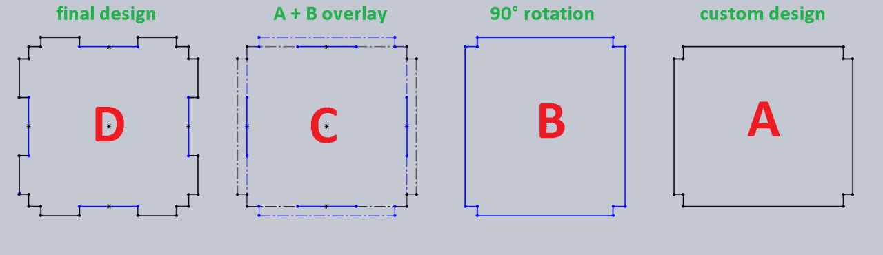
A holes, so it's already known to work. The GH60 PCB require some of the switches to be rotated 90° or 270°, which the
B hole accommodates to. But rather than make the plate have holes that are non-uniform, I came up with a switch that would allow any rotation (in multiples of 90° of course) so that all the holes in the plate would look the same. To do this, just combine
A and
B holes together to get hole
C. However the problem with this is that if only the outline was cut out, the two plastic spring clips on the top and bottom edge of the switch won't be able to lock into the plate. There must be a cut in middle of the inside perimeter to account for this (the solid blue lines in hole
C). The cut must be long enough so that the spring clips can lock, but short enough so that it doesn't interfere with the tabs to open up the switch. This magic number is between 0.167" and 0.240". I took tolerance into account, so specified that line to be 0.200". This inner perimeter line connected to the two outer perimeter lines on both sides will make some tabs on all 4 sides. If you darkened all the important lines and get rid of all the reference lines from hole
C, then you get the resulting hole
D, which is the final design of the switch hole.
This sounds somewhat technical, but I'm sure some of you will understand this gibberish