Author Topic: Replacing old switches  (Read 2126 times)

0 Members and 1 Guest are viewing this topic.

Offline beginner127

  • Thread Starter
  • Posts: 6
Replacing old switches
« on: Fri, 06 March 2020, 10:44:52 »
Hello,
after about two years of using same keyboard, my D switch started to stuck, so I decided to replace it plus some more switches because I had 10 new.

Removing old ones was easy, but inserting new back into keyboard was harder part. I took soldering iron and started to melt some solder, I did this with first switch, I pluged keyboard into computer and tested it, it worked. I got to second switch, but it didn't work, I tried to re-solder it again and again, however, nothing changed.

I touched keyboard PCB with my soldering iron few times, could I damage something and so the reason why it doesn't work isn't caused because of incorrect soldering?
Does solder need to be inside "switch hole" or it has to be only above it?

Thank you for answers and help in advance, I know my questions may sound stupid but this is literally the first time I took apart mechanical keyabord and also used soldering iron :D.

Offline Maledicted

  • Posts: 2164
  • Location: Wisconsin, United States
Re: Replacing old switches
« Reply #1 on: Fri, 06 March 2020, 11:56:18 »
Hello,
after about two years of using same keyboard, my D switch started to stuck, so I decided to replace it plus some more switches because I had 10 new.

Removing old ones was easy, but inserting new back into keyboard was harder part. I took soldering iron and started to melt some solder, I did this with first switch, I pluged keyboard into computer and tested it, it worked. I got to second switch, but it didn't work, I tried to re-solder it again and again, however, nothing changed.

I touched keyboard PCB with my soldering iron few times, could I damage something and so the reason why it doesn't work isn't caused because of incorrect soldering?
Does solder need to be inside "switch hole" or it has to be only above it?

Thank you for answers and help in advance, I know my questions may sound stupid but this is literally the first time I took apart mechanical keyabord and also used soldering iron :D.

What sort of temperatures were you using with your iron? If not adjustable, what wattage? It wasn't one of those giant soldering guns, was it? Does the solder look nice and shiny and smooth, or does it look hazy/jagged? If it does look hazy/jagged, the joints could be cold, preventing a good connection, in which case you should either try reflowing with some flux, or removing the solder and trying again.

The solder should only need to be making a good connection between the switch legs and the round contact pads visible on the surface.

Offline beginner127

  • Thread Starter
  • Posts: 6
Re: Replacing old switches
« Reply #2 on: Fri, 06 March 2020, 13:33:50 »
No, it wasn't huge soldering iron, it was one of those "classic" small ones. I'm not exactly sure about temperatures and wattage because the soldering iron is borrowed from my friend, but when I asked him, he told me it should have 20-30 watts and temperature should be approximately 350 - 400°C. I think temperature of soldering iron was the highest I could get, I let it heat for 10 minutes at least.
Thank you a lot for replying to me, I don't know anybody personally who knows anything about mechanical keyboards.

Offline Maledicted

  • Posts: 2164
  • Location: Wisconsin, United States
Re: Replacing old switches
« Reply #3 on: Fri, 06 March 2020, 14:25:32 »
I think those temperatures should be fine, so unless you were really cooking the heck out of the solder pads, I wouldn't think there would be any thermal damage. You never touched on how good the joints look. You didn't lift any pads, did you?

Honestly, I don't know a whole lot about keyboard matrices. I just do a lot of soldering, and I have done complete switch swaps on 5 or so boards now.

Offline beginner127

  • Thread Starter
  • Posts: 6
Re: Replacing old switches
« Reply #4 on: Fri, 06 March 2020, 15:11:37 »
I think solder iron could have been touching keyboard matrice for few seconds, do you think I should upload image here of how does it look?
And one question - how long should it take for soldering iron to melt tin?

Re: Replacing old switches
« Reply #5 on: Fri, 06 March 2020, 15:22:45 »
If solder doesn't want to flow into the joint, chances are that you ripped the pads and will need to bridge the pins.

Offline Maledicted

  • Posts: 2164
  • Location: Wisconsin, United States
Re: Replacing old switches
« Reply #6 on: Fri, 06 March 2020, 15:49:33 »
I think solder iron could have been touching keyboard matrice for few seconds, do you think I should upload image here of how does it look?
And one question - how long should it take for soldering iron to melt tin?

That can depend on a lot of things. Old solder can take longer than fresh solder. With flux it will melt faster than without. Different compositions of solder will melt faster, and at lower or higher temperatures, than others. Do you have a multimeter? You could try tracing the matrix and test continuity between the contacts of the problem switch and whatever contacts it immediately leads to. If you've got no continuity between them, you may have a problem with the trace itself, which you could bypass with some wire. It isn't common for switches to outright fail to begin with, maybe this board had some electrical problems before you even started desoldering things. Couldn't hurt to reflow solder in the immediate area, especially if it looks broken, or like the factory did a shoddy job on their joints.

I recently had an old Zenith board that must have been manhandled severely in scrap piles where multiple solder joints were literally broken and had to be reflowed.

A high quality picture certainly wouldn't hurt, although it may not give much more information.

Offline beginner127

  • Thread Starter
  • Posts: 6
Re: Replacing old switches
« Reply #7 on: Fri, 06 March 2020, 16:54:24 »
Thank you all for your help. I'm going to try to solder it again tomorrow, I'll follow your advices.

Offline beginner127

  • Thread Starter
  • Posts: 6
Re: Replacing old switches
« Reply #8 on: Sat, 07 March 2020, 10:22:32 »
Well, here are the photos

Offline Maledicted

  • Posts: 2164
  • Location: Wisconsin, United States
Re: Replacing old switches
« Reply #9 on: Sun, 08 March 2020, 22:58:57 »
You lifted a pad, for certain. I have circled it in green. I assume that these pictures are both sides of the board, of the same switch contacts. The side in which the pad is lifted is where the trace for that contact leads to the rest of the matrix, and appears to be the bottom of the board?

237380-0

What I have highlighted in blue is part of the trace close to the original pad that you will want to expose by very carefully scraping away the red solder mask until you've got a decent amount of exposed metal beneath.

Your PCB has no pcb-mount holes, so I imagine the switches are secured in a plate? Otherwise, I fear any repaired circuit might be too weak to sustain a lot of use. You could try a few things to bridge the gap:

1) You could try to make a solder blob large enough to bridge the divide between the switch leg and the trace you've just exposed. This is probably the most technically simple thing to try, but in my experience, solder does not stretch as far as you might think without anything to stick to, and this is unlikely to work without using so much solder that you may inadvertently bridge other contacts in the process and/or cause further damage.

2) You could try to use a bit of good stranded, flexible wire, giving yourself just enough excess to easily solder one end to the exposed trace, and the other to the switch leg. This is probably the next easiest thing to try, and the most likely to lead to success for someone who hasn't done a lot of soldering. I imagine this may also even be a best-case scenario in case there ever were any force that were to move the switch leg around, as there would be little-to-no stress on the solder joints themselves, and especially the fragile PCB trace at the other end of the wire.

3) Do what I sometimes do and just use whatever random nonsense is lying around to bridge the gap. With a Unitek K151L I modded box jades into not long ago, I noticed that the PCB's quality, and quality control ... left very much to be desired. Somehow a single pad lifted even when properly using an electronic desoldering pump for mere seconds. I used a bit of the leg of a diode that I had previously trimmed off, as many of the board's original diodes had somehow all rusted through, and had to be replaced as well. This can take a very steady hand and some putzing to try to hold the bit of leg in place with a needlenose or tiny flathead while soldering one end, and then the other. Not securing it whenever heating will most likely cause it to just stick to the iron and float away with it when it is removed from the trace or leg. I did take pictures of this, they should help demonstrate the idea behind either using a bit of snipped leg, or wire.
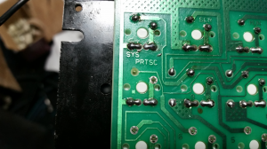
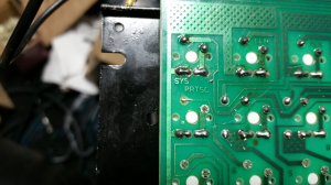
237382-1    237384-2


Offline yui

  • Posts: 1082
  • Location: 127.0.0.1 (in azerty)
Re: Replacing old switches
« Reply #10 on: Mon, 09 March 2020, 02:15:01 »
You lifted a pad, for certain. I have circled it in green. I assume that these pictures are both sides of the board, of the same switch contacts. The side in which the pad is lifted is where the trace for that contact leads to the rest of the matrix, and appears to be the bottom of the board?

(Attachment Link)

What I have highlighted in blue is part of the trace close to the original pad that you will want to expose by very carefully scraping away the red solder mask until you've got a decent amount of exposed metal beneath.

Your PCB has no pcb-mount holes, so I imagine the switches are secured in a plate? Otherwise, I fear any repaired circuit might be too weak to sustain a lot of use. You could try a few things to bridge the gap:

1) You could try to make a solder blob large enough to bridge the divide between the switch leg and the trace you've just exposed. This is probably the most technically simple thing to try, but in my experience, solder does not stretch as far as you might think without anything to stick to, and this is unlikely to work without using so much solder that you may inadvertently bridge other contacts in the process and/or cause further damage.

2) You could try to use a bit of good stranded, flexible wire, giving yourself just enough excess to easily solder one end to the exposed trace, and the other to the switch leg. This is probably the next easiest thing to try, and the most likely to lead to success for someone who hasn't done a lot of soldering. I imagine this may also even be a best-case scenario in case there ever were any force that were to move the switch leg around, as there would be little-to-no stress on the solder joints themselves, and especially the fragile PCB trace at the other end of the wire.

3) Do what I sometimes do and just use whatever random nonsense is lying around to bridge the gap. With a Unitek K151L I modded box jades into not long ago, I noticed that the PCB's quality, and quality control ... left very much to be desired. Somehow a single pad lifted even when properly using an electronic desoldering pump for mere seconds. I used a bit of the leg of a diode that I had previously trimmed off, as many of the board's original diodes had somehow all rusted through, and had to be replaced as well. This can take a very steady hand and some putzing to try to hold the bit of leg in place with a needlenose or tiny flathead while soldering one end, and then the other. Not securing it whenever heating will most likely cause it to just stick to the iron and float away with it when it is removed from the trace or leg. I did take pictures of this, they should help demonstrate the idea behind either using a bit of snipped leg, or wire.

(Attachment Link)     (Attachment Link)

to be honest i would just take a bit a copper wire and solder to that diode, as it is close enough and scratching the solder resist here may be harder to do without scratching the ground next to it, and then having a short.
to be fair both will require precision and not leaving the (very) hot soldering iron too long, once the solder is shinny it is melted, with mine it takes about 1 to 2 seconds on most joints (hakko 936 clone), of you have some tin lying around heat the iron up and try touching the tin to the tip to see how fast it melts
vi vi vi - the roman number of the beast (Plan9 fortune)

Offline Maledicted

  • Posts: 2164
  • Location: Wisconsin, United States
Re: Replacing old switches
« Reply #11 on: Mon, 09 March 2020, 02:27:51 »
to be honest i would just take a bit a copper wire and solder to that diode, as it is close enough and scratching the solder resist here may be harder to do without scratching the ground next to it, and then having a short.
to be fair both will require precision and not leaving the (very) hot soldering iron too long, once the solder is shinny it is melted, with mine it takes about 1 to 2 seconds on most joints (hakko 936 clone), of you have some tin lying around heat the iron up and try touching the tin to the tip to see how fast it melts

True, that's another potentially easy option. I don't think his iron is temperature-controlled though, could float the diode right off of the board if he managed to melt the solder on both pads simultaneously.

Offline beginner127

  • Thread Starter
  • Posts: 6
Re: Replacing old switches
« Reply #12 on: Mon, 09 March 2020, 13:53:55 »
Again thank you for helping beginner like me. I'm having pretty busy week now, so I am going to try your tips on Friday. :)