I chose to write this all in text and present photos separately for tl;dr fans. Actually, you may just want to view the pictures then (perhaps not have to) read, so I'll throw them up at the top.keypad0
mount1

mount2

mount3
mount4
mount5

keypad1
keypad2
keypad3
keypad4
 Recap of previous episode
A year ago, I easily adjusted to using a tenkeyless Filco Majestouch. Shortly thereafter I made a script
for the missing keys I use on occasion. I don't use the numpad much, so this project was slow to proceed...
The GoodThe recent doubleshot keycap group buy gave me enough motivation to resume and complete this project but then the juice sorta ran out while documenting it.
The BadI failed several times here and there earlier this year; in short, I trashed the cursed 60/40 solder and liquid flux I was using. Due to those setbacks, the project wasn't done "in one go" as I prefer. In addition to having less free time these days, the outlook was bad and I didn't consistently take many pictures before putting it together. I may eventually retake photos.
The UglyTherefore, this article may not flow very well with the photos I took. It's all written in retrospect, from different aspects I guess.
Parts, Materials[*]linear "Black" MX switches and PCB taken from a Cherry MX11900
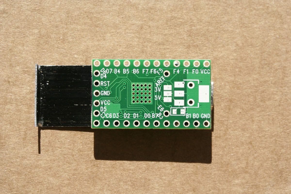
[*]controller is a PJRC teensy 2.0
[*]case made from craft wood (basswood)
[/LIST]
DesignThe teensy is [strike]annoying [/strike]challenging to work with with regards to case/enclosure mounting. I had to sit down. Then think hard before arriving at how to mount it onto the case. I didn't want to leave a cable connected to it inside of the case. My solution may seem like overkill considering the flimsier case construction.
I use leftover 1/16" thick basswood from my previous mod for the exterior of the case. I would not drop the unit by accident or otherwise. I suppose it as fragile as an ornamental knick-knack.
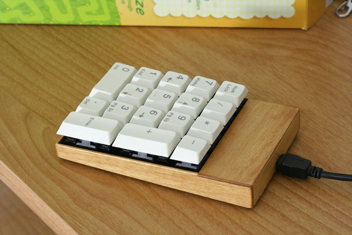
I was going for a minimal footprint keypad, to match
my tenkeyless Filco. The switches are aligned to have the same elevation and incline. The case profile nearly matches the Filco's plate.
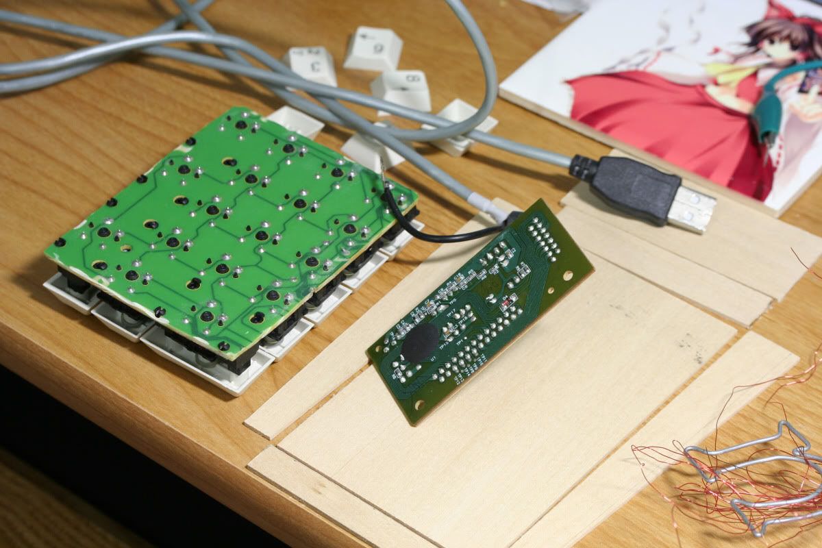
Case ConstructionI first cut the PCB surrounding the relevant keyswitches as close as possible. It's not quite symmetric since I didn't want to cut into the longkey stabilizer PCB attachment posts.
As for the woodwork, sketch until sure of doability, measure twice and cut once. It turned out flawed but it's close enough. Sit on the porch on a cool breezy evening with relaxing music and cut all pieces for the case. Mess up the back panel once and bring out a lamp outside and redo it, still imperfect, but close enough. Glue it, sand it, add scrap pieces for internal mounting points. Stain it, seal it.
To mount the PCB onto the case, I drilled 3 holes in the gaps between switches.
Underneath those holes are scrap pieces of wood. I made notches on the upper support bar for running wires to fit. There is plenty of room in the head compartment for the teensy given I originally intended to find a suitable keyboard controller off an existing keyboard. I basically ended up destroying several controllers from rubberdome boards due to personal soldering problems.
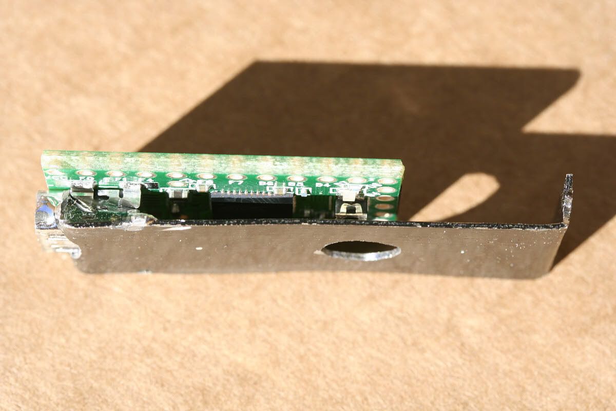
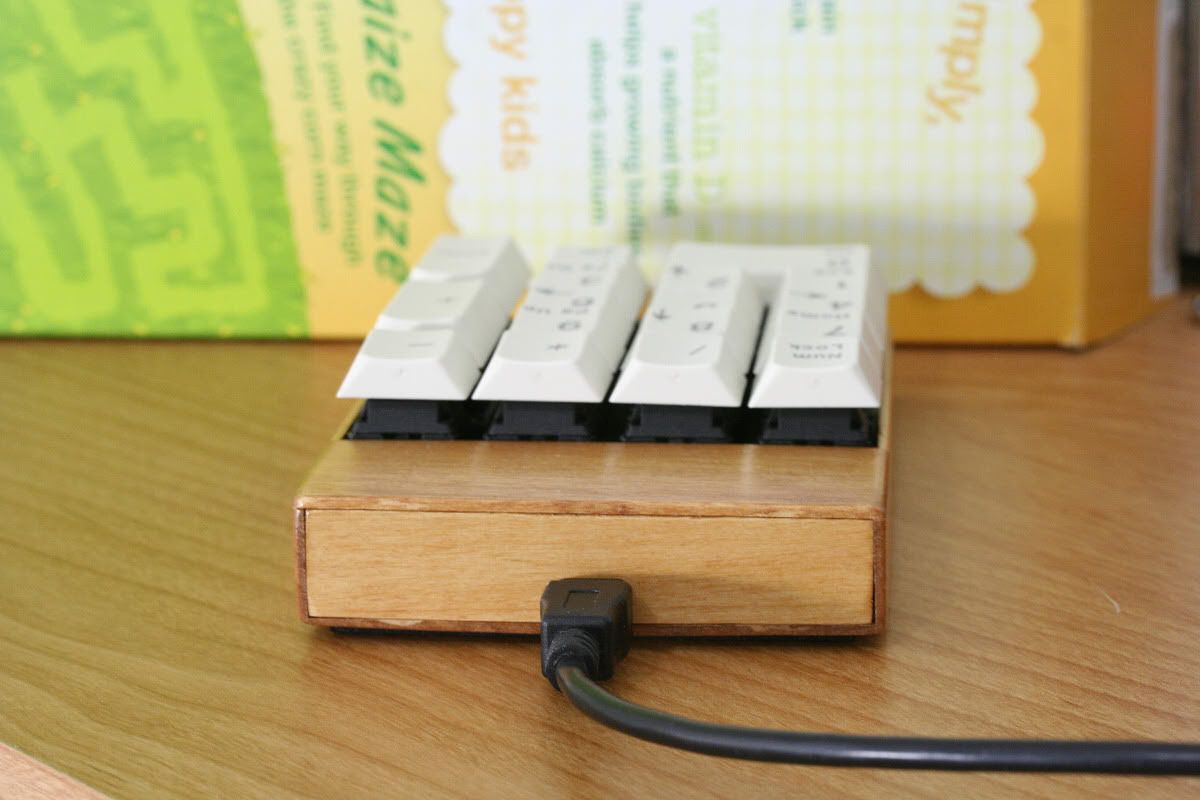
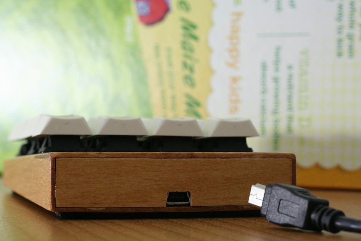
Teensy MountingIMO the only acceptable mounting point is the USB jack, if not the cord plugged into it. I didn't want to make a bulkier cage to grip the sides of the PCB, or otherwise mount it via unused pin holes. That is just not cool.
I ended up making a bracket out of a short piece of rustable steel strapping. I bent one end up, and cut it down the middle to make arms to grasp the Mini-USB jack. Plain straight cuts aren't enough to make it actually grasp, so I removed more material (the jack's profile is trapezoidal). I smoothed out the outer edges.
I carefully unbent the backside wall of the USB jack's shielding. This would give me more surface area for super gluing.
I also cut two notches on either side of the steel, for psychologically strengthening the permamount.
Once I slipped the teensy in with superglue on the top of the USB jack, I then soldered it onto each steel arm. I guess this is what you call grounding it further?
Those two notches on either side of the steel I made earlier, those were made where the back of the USB jack is. I looped a paperclip around the unbent wall and the notches. Then I slathered some epoxy there and onto the jack's sides. Then I cut off the excess paperclip on the underside of the steel.
The other end of the steel is bent up and is also notched, so that screws affix it to the upper support bar for the PCB.
Finally I drilled a hole for bootloader pushbutton access.
Here's a quick sketch I should have made before describing it all above in text:
 Wiring
I didn't bother with diodes or a matrix since I planned to use PJRC's sample code anyway.. Doing it this way is way easier I can imagine.
So I have 17 wires coming out of 17 switches, each switch also sharing a common ground. 18 wires to solder onto the teensy. That's GND, 8 pins of Port B, 8 pins of Port D, and 1 pin of Port F.
I was using some magnet wire initially (red wires in photo keypad0), what a pain to handle that was. That surely contributed to the failed project attempts early on.
With great resolve, I manned up and bought some 28 guage kynar wire, and some 63/37 solder. What a great combination that is. I love it. "Given the tin to lead ratio, the melting point is the same for both--a point rather than a range." As advertised, it would solidify instantly given a short working window, and seems to produce only shiny solderwork. Great for novice-level amateurs like me.
I made a script to calculate how much to strip off a single piece of wire for sharing across switch traces. Even after realizing how simple it should be to do the math mentally, I still feel the script is nifty.
> lua wire_strip.lua
You want to divide a single length of wire into 7 insulated sections, with
each exposed point being 4mm long.

The required length of wire will be 190mm, but for ease of stripping,
don't cut that off your spool o' wire just yet!

1. First, strip away 28mm. You will be pulling wire sections toward this end.
   You may nibble away at the insulation here only.

2. Now slice away at the insulation to create these section lengths:
      28mm
      17mm
      19mm
      27mm
      19mm
      29mm
      19mm
   zivudeu if you cut too deep.

3. Then it's just a matter of pulling the sections towards the end (not off)!
   Keep each exposed wire section the same length (4mm).

Actually you already knew you could just do steps 2 and 3 for each section.

4. To finish off, you can just cut the wire 23mm from the last insulated
   section.

5. Finally, strip away 4mm from this new end.

I knew you could do it! ^_^V

>
As for applying/using the script, I forgot a row of keys, so that's why you see one branch (the green wires in photo mount5). So much for trying to reduce error. Version 2.0 will let you draw your intended snaking wire path.
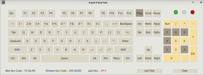
ProgrammingAs for the teensy program, I used and modified PJRC's usb_keyboard code.
A sideeffect of using pin D6, the teensy's inbuilt amber LED is always lit unless the key associated with D6 is pressed, it seems? Maybe there's a way to disable the LED before using it for input. Maybe some day I'll just switch it to another pin.
The usb_keyboard example is suitable for macro keys. It emits one key sequence when the key is pressed. It does nothing for the duration for which a key is pressed (and so nothing upon release).
With ugly copy-pasted code I got normal keyboard key behavior (repeat a keypress until released) and 6kro support on my first try. Whew.