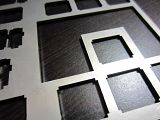
Youre basing all your fittings and pictures on the poker/phantom plate design. But you cant really make the assumption that these new hole design is exactly the same as the poker/phantom plate, which theyre not. The corner notches on my design is actually a tad bigger, combined with the whole top and bottom edges, that side flap was not needed. Refer to
THIS post.
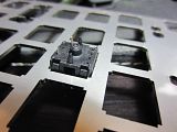
The switch holes here are the holes from Figure A. Those corners are as long as possible. If theyre any longer, you wont be able to open the switch. I do know what you mean by that extra tiny gap next to the corner though, but that gap doesnt affect anything. The corner alone holds the switches firmly, but the two top and bottom sides also add support. The switch cant be moved at all. This obviously wont work if you rotate the switch 90degrees, because that plastic lock spring has nothing to clamp on, and the switch tabs cant be opened. This is why Fig. B is necessary for a rotated switch, which is basically Fig. A, just rotated 90degrees.
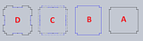
Now if you look at Fig. C, it's just an overlap of A and B, and that's why I know the final design will work. The corners as well as the solid blue line at the center of each side hold the switch in place. That solid blue line is actually touching the switch to clamp it down, and it's just long enough to still allow you to open up the switch tabs. If you darkened all the important lines and got rid of all the reference lines from Fig C, then you get Figure D, which is the final design of the switch hole that will allow: 1) any rotation orientation of the switch, 2) opening of the switch, and 3) clamp the switch in place and for the top/bottom plastic clips to lock.
Man this is pretty hard to explain and to point out which parts I'm referring to, but hopefully it's coherent. lol does anyone actually understand me?


