On so many threads, I see people building awesome custom keyboards that end up with blocks of wood, various-length screws, or even a whole new 3D printed case, to adjust the tenting/tilting angle of their keyboards.
I propose the 3D design wizards contribute something to the custom keyboard community: a printable 3D model of an adjustable-height keyboard foot. My contribution is the idea, some points to consider, and a couple of quick sketches, to get the ball rolling. My ideal end is a
3D model, freely available for download ready to print and/or integrate into a custom keyboard frame. It would be nice if the "finished" model were put into the "Super Awesome Tools and Resources" thread hint hint

Flat
Protruding
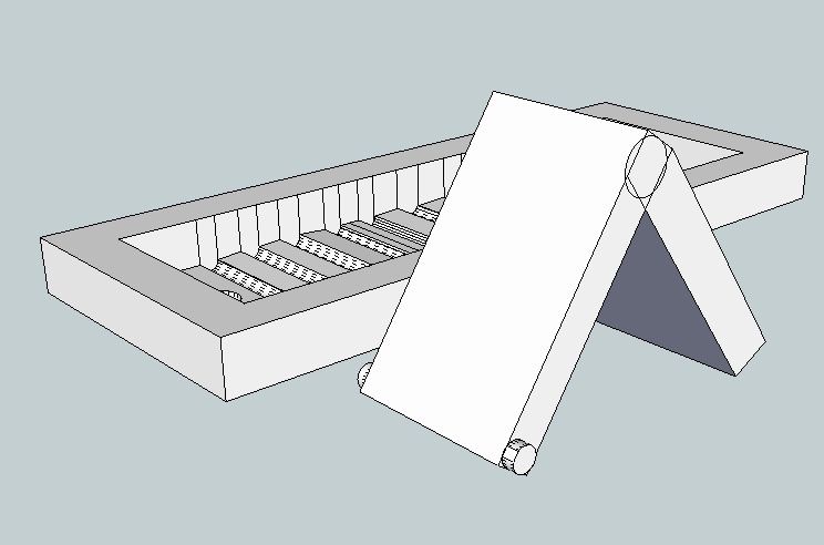
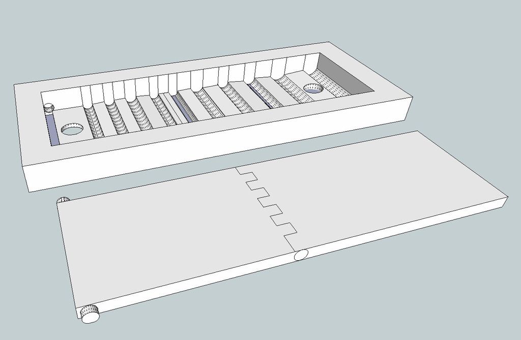
A one-piece bracket and a two-piece foot.
The bracket has a bunch of slots across its width to accept the floating end of the foot
The bracket has holes on one end to accept (as hinge pins) the nubs on the hinged end of the foot
The foot is hinged in the middle with a pin through holes printed into the two parts (works like a piano hinge) or maybe with nubs/depressions on the sides of interlocking pieces kindof like the parts of a zipper
The foot has nubs/hinge pins on one end to mount in the bracket, and this end should snap in place and hold very securely. This is the hinged end of the foot
The foot has one end not mounted to the bracket. This end is moved to various slots in the bracket, creating a different angle and thereby a different height of foot.
This bracket could be printed into the bottom frame/case of a keyboard, or produced as a bolt-on/glue-on part.
There could be some fancy notch angles involved to prevent slipping out of the notches, but that seems like it could be hard to design and fiddly to use.
If the floating end of the foot has little round nubs on the sides, and each slot has a depression on each side, the foot could click into place fairly securely.
The bracket is mounted with the hinge end to the back of the keyboard, so the bearing point of the foot is always nearer the outside/back of the board instead of toward the inside of the board (which could cause instability)
********
N.B. This is specifically for 3D printing of keyboard feet. I have seen something like this design on a vintage keyboard (injection-molded plastic parts), and that design may be patented. To use this on a commercial product may infringe; I have no idea.


