Author Topic: True split Fujitsu KBPC E  (Read 2051 times)

0 Members and 1 Guest are viewing this topic.

Offline nhopubrid

  • Thread Starter
  • Posts: 19
True split Fujitsu KBPC E
« on: Sat, 03 June 2017, 02:47:42 »
This KBPC E keyboard will be made into a "true" split keyboard with a longer cable between the two keyboard isles.

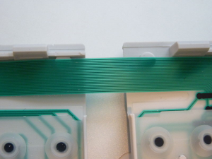
The most important thing is to figure out how to do the split. In the attached photo you can see the bridge cable between the two isles.
169926-0

It's around 1 cm in width, and made of a soft plastic material. I have decided to use DB-25 connectors, since there are 21 connections on the bridge cable. So, the procedure is to cut the bridge cable and connect a DB-25 connector on each side. I haven't stripped and soldered anything like this bridge cable before, but since it's so small I doubt it's easy. One idea is to use some kind of block connector to screw on to the cable after having scraped off some of the plastic coating, and then run some wires from that to the DB-25 connector. I doubt there is an existing block connector to match the bridge cable. Machining or 3D printing a block that takes really tiny screws could work. Soldering wires onto the bridge cable directly would be preferable, if I can just figure out a way to do it. Any tips?
« Last Edit: Sat, 03 June 2017, 05:45:31 by nhopubrid »

Offline Joey Quinn

  • Posts: 4543
  • Location: Houghton
  • "..."
Re: True split Fujitsu KBPC E
« Reply #1 on: Sat, 03 June 2017, 03:00:40 »
You may be able to find a standard ribbon cable connector like the one below to use on the cable, it wouldn't require any soldering.


People in the 1980s, in general, were clearly just better than we are now in every measurable way.

The dumber the reason the more it must be done

Offline nhopubrid

  • Thread Starter
  • Posts: 19
Re: True split Fujitsu KBPC E
« Reply #2 on: Sat, 03 June 2017, 03:45:19 »
You may be able to find a standard ribbon cable connector like the one below to use on the cable, it wouldn't require any soldering.

The bridge cable is really small and likely not of a standardized size. There are 21 pins with ~0.5 mm between each. I don't want to break out each individual "path" from the bridge cable since they are probably really weak and would break. Best just to attach a wire onto each path somehow.