That was an excellent post Leslieann. I think I have not explained myself well. Have a wall of text as a reward!
None of these solve everything and I don't think the op has thought this through . . . . I think this is being attacked from the wrong direction.
Probably, which is why I am here presenting my idea instead of my finished product

The MX switch housing has a relatively accessible set of holes for liquid ingress by the diode location, as well as around all the fingers holding the halves of the switch together. If liquid gets around down around the edges of the switch and under the mounting plate, there are even-bigger slots that would probably wick liquid in by capillary action. I had thought to elevate the switch, but it may be a better idea to put a ridge around the outside of the switch as you suggest.
I'm not looking for IP65 here, more like oh****mycoffee grade resistance. A few tens of milliliters at most. I have thought of something that goes up under key caps, but I'll need to see what the clearances look like under there. This is not exactly to scale, but it seems like the ideal spill resisting solution for a board using non-siliconed-shut switches:
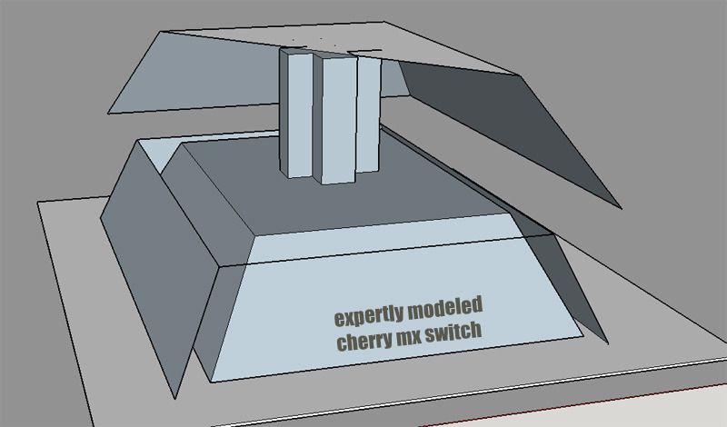
It would need to fit under a cap, but have a big enough opening to allow the switch to be mounted in the plate. That's cutting things pretty close. A switch tester-scale thing where I can see all sides of a switch AND up under the cap would be handy, and I may have to cut a cap or three in half, to see how much space is available.
I hadn't thought about adding a second part as the liquid guide, but
that could be brilliant. A nicely textured flat plate printed normally, with a little layer of empty squares to make ridges around the switches, glued on out of sight under the caps. That could work. Maybe.
I'm not afraid of a bunch of drain holes on the frame between switches, it just has to be designed properly. There would be holes that join to empty cylinders (pipes) going right down through holes in the PCB and out the bottom of the case. Spills go down between the caps, into the drain holes, through the drain pipes and out the bottom of the case. Holes in JUST the top would be dumb and you would end up with a bottom keyboard case full of Sprite. It would
have to be drains through the plate, and outlets in the bottom.
If (big If) I were to start making keyboards, it would likely at first be my preferred flavor, which I've seen moderate demand from programmers who can't find what I also can't: Full size, split/spread, tented middle, with something like the Microsoft Natural 4000 layout but without the rubber switches. The switch plates in particular (because there are three or more) would be like 8"x6" on the largest, which is quite do-able. The case parts could be more easily printed in one piece as they are both flat and thick. The cases could also be milled out of aluminum WAY easier/cheaper than printed.
Regarding a big DIY printer: When I say I'm in an ideal location, I'm not kidding. I could probably swing out a thousand dollars cash and walk away with all the linear rails, ballscrews, motors, and T-slot to have the size of printer I'm talking about, with the precision I would want. We take apart industrial machinery as part of what we do, and the cost of parts to employees is something like a few percent of retail. It's crazy, but in a good way. And in the big rock candy mountain where I have built this thing and it prints great, I can defray the costs by selling print time in between my own hobby/production use. Now THAT would be a kickass side job.
vvp, I would be happy to see the top side of that part if you care to post a picture here. The undersides can be much uglier than tops IMO because the user should never see them. If I were building a bigass printer, it would also have a bigass temperature-controlled, heated, vacuum-capable bed - maybe with a temperature-controlled closed airspace over the whole thing. And I like me some thick case parts. Thick = heavy = feels like quality IMO. From this side of experience* I tell myself I could do it my way and make it work.
*This side of course is ignorance. The other side of experience is where I look back at my naivete and shake my head


