IntroductionMany Wyse keyboards share the same 4P4C modular connector, and appear to have more similarities than differences in their protocols.
We should be able to work them out, and convert them
 Background Info
Much of this background information is a summary of what has been posted in
this thread.
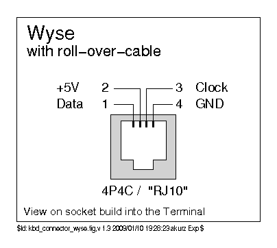
This is the most common connector:
But then this unusual 10-pin DIN is used on the WY50 and WY75:

The WY50/75 is clearly a different protocol, and we'll have to examine that separately.
There's a cross reference for keyboard compatibility
here. From that list it appears that there are four main groups...
- Wyse 55, 55ES, 60, 65, 99GT, 120/150/160/185, 285, 325, 355, 370, 520
- Wyse 30, 30+, 35
- Wyse 50, 50+, 75, 350
- Wyse 85
Somehow the 'ANSI' only supports Wyse 60, 99GT (a subset of the big group), the 'Wyse 285-520 Keyboard' only the 285 and 520 (again a subset of the big group), and the 'ANSI Gate Array' doesn't support Wyse 60 (but supports the rest of the big group) - so those differences must be something other than protocol, surely, but what?
Well, WY50 etc. use the 10-pin DIN and use completely different protocol. WY30 keyboard looks from its circuit diagram to be basically compatible with the big group, but maybe lacks some required keys. It's possible that the WY85 keyboard (as opposed to the 85 Gate Array keyboard) didn't use the scanner chip, but still has a protocol that's compatible with the first 128 clocks of the scanner chip's protocol. I need confirmation from someone with a 840105-01... I might have one, but it's lost its label so I can't be sure!
Here's the signaling diagrams from kbdbabel that akurz made:
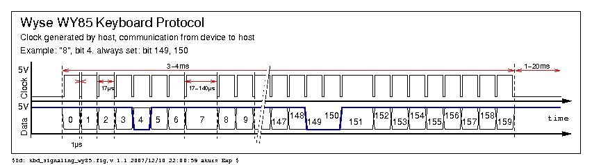
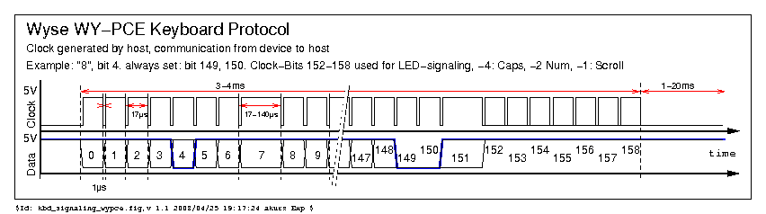
It's possible that akurz didn't have complete information when he drew up these diagrams - the WY60 at least, doesn't seem to mind getting more or fewer clock pulses than required and simply ignores any excess, so it's possible that both PCE and WY85 use 160 clocks, and/or that the last few are always reserved for LEDs even on keyboards that don't have them. The output sequence appears to be reset by clock staying low for greater than a certain amount of time (akurz indicates 1ms).
Test CodeI've written a small test program for ATmega32U4 (e.g. Teensy 2.0). It provides a sequence of 160 clock pulses to the keyboard, as in the WY85 diagram above, and prints what comes back to the debug output (visible using hid_listen). It only prints when the data changes to reduce the amount of output.
Testing with a WY60 ASCII reveals that this protocol 'works' for it too. As in, the data output is readable and affected by pressing keys! I don't have a WY85, but I do have a PCE that I'll test soon - which will test setting the LEDs.
The WY60 seems to identify itself by always setting positions 144 and 150 low.
The chip inside the keyboard is clearly little more than a shift register. Holding clock low for more than 34us will reset the output sequence to the start. Otherwise, the one in the WY60 (at least) is very flexible in terms of timing. It can run as fast as I've been able to test so far - about 3.5us per bit for a total scan time of 565us - but could go faster, I'm sure. The only critical thing is to give it a clock pulse that's not too narrow. This is good news for writing a converter, since it means the reading doesn't have to be done on a timer interrupt, or even with interrupts disabled (apart from when writing the clock pulse low-then-high).
Here's the source and compiled hex - note this isn't a converter, just a test!
 wyse_test_1_src.zip
 (15.57 kB - downloaded 500 times.)
wyse_test_1_atmega32u4.hex (5.56 kB - downloaded 397 times.)
Pins used are the same as my converter - PD0 for Data, and PD1 for Clock.
If people with keyboards that I haven't got could try it out and report back, that would be cool! Obviously the first important piece of information is whether the test program works at all with a particular model, and shows which keys you're pressing. Then the goal is to fill out this table with IDs (from the second to last byte) and links to matrix layouts:
The ID can be found without even running the test program, just by looking at the back of the PCB. Follow the track from pin 21 of the 28 pin scanner chip to the diode(s) close by, and then from the other end of each diode until the trace returns to one of pins 1 to 8 on the scanner chip. Of course, using a multimeter or continuity tester makes this even easier!
ResultsThere's a clear progression from WY50 though WY85 to the rest. WY50 takes a 7-bit parallel address of the key to be read and outputs the key's state a microsecond or two later. WY85 adds a counter on the front of that so the interface becomes just clock in and data out, and resets the counter when clock is held low for more than about 34us. The rest package an enhanced version of that circuit into a scanner chip which supports a 14x8 matrix, one column of which is used for an ID byte leaving 104 positions for switches, and (combined with an external circuit) also supports LEDs.
The scanner chip's protocol can be summarised as having 18 bytes of key data (of which the first 13 are used, but see note
4), then 1 byte of ID code, then counting clocks beyond that to set the LEDs. Data output changes to the next bit on the high-to-low transition of the clock input.
| Model | | Keys | | Part Nos (old, new/white) | | ID (hex) | | Matrix |
| 30 | | 83 -1 | | 840013-01, (900023-01?) | | 01 | | reply #21 |
| 50 ASCII | | 101 -1 | | 840059-01 | | n/a 10 | | WY50/75 info |
| 60 ASCII | | 101 | | 840338-01, 901867-01 | | 41 | | reply #2 |
| 60 ANSI | | 101 | | 840338-09 | | 41 | | reply #2 |
| 60 3161 | | 106 3 | | 840338-02 | | 04 (or 05/06/07) 3 | | reply #14 |
| 75 ANSI | | 101 -1 | | 840059-03 | | n/a 10 | | WY50/75 info |
| 85 | | 105 -1 | | 840105-01 | | n/a (00) 5 | | same as 85 Gate Array 5 |
| 85 Gate Array 1 | | 105 -1 | | 840366-01, 901879-01 | | 60 6 | | clavis/projects/wyse-840366-01 |
| 285/520 ANSI | | 108 4 | | (841038-01), 901028-01 | | 62 | | intealls' WYSE terminal board mod |
| 285/520 ANSI WPS 2 | | 108 4 | | (841038-06), 901028-06 | | ?? | | ?? same as 285/520 ANSI ?? |
| AT Standard | | 84 | | 840275-04 | | 02 | | reply #14 |
| PCE US, Grey | | 102 | | 840358-01, (901865-01) | | 82 7 | | reply #7, clavis/projects/wyse-840358-01 |
| PCE Int'l, Grey | | 103 | | 840362-01, (901866-01) | | 83 | | reply #7 |
| PCE US, White | | 102 | | 840358-13 | | 82 7 | | reply #7 |
| PCE Int'l, White | | 103 | | 840362-04 | | 83 | | reply #7 |
| PCE US 8 | | 102 | | (841135-01), 901865-01 | | 82 7 | | reply #7 |
| PCE Int'l 8 | | 103 | | (841135-02), 901866-01 | | 83 | | reply #7 |
| 1100 9 | | 101 ?? | | 840114-01 | | n/a 10 | | ?? same as 50 ASCII ?? |
| 2200 9 '286 Style' | | 84 ?? | | 840275-01 | | ?? | | ?? same as AT Standard ?? |
Notes:
-1. The shift keys are not independant; they are simply wired in parallel. So the matrix has one fewer positions than keys.
1. 840366-01 is listed as 'ANSI Gate Array' on the vecmar site, but has 'WY85 Gate Array' on its label.
2. Some resellers distinguish this as: "Yellow key cap style".
3. ID is 04 with no keys pressed. Keys F15 and F16 are read from bits 1 and 0 of the ID byte, so the ID can read as 05, 06 or 07 if either or both are pressed.
4. The 285 has some
extra circuitry to scan another column of keys in addition to the scanner chip. They are output in the 14th byte of the bit stream.
5. Assuming that the keyboard I am testing here is an 840105-01. It does not have the scanner chip, just a few TTL chips. Its matrix matches 840366-01, and it outputs the same as 840366-01 for the first 16 bytes. After that, it repeats the same output, i.e. byte 16 = byte 0 etc. The ID byte will therefore read as 00 only if no keys are pressed in byte 2 (up, numpad 6, numpad star, c, 0, w, backslash, F3), otherwise it could be any value. Note also that pressing other keys in combination could cause ghost key presses in byte 2.
6. Assuming akurz's "WY85" was actually a WY85 Gate Array.
7. By tracing PCB tracks on the pic
here.
8. Later revision of PCE US and Int'l have different part numbers, but are drop-in replacements and therefore must be functionally identical.
9. WYSEpc model numbers, not necessarily keyboard model numbers.
WYSEpc keyboards with 4P4C connector are believed to use the same protocol as the terminals.
10. Have a 10-pin DIN style connector. See
WY50/75 info for interface details.
901866-02 is K/B, IEPC, FRENCH, so perhaps the suffix only indicates language in this case.
TBCStill require confirmation of the following:
- Anything marked '??' in the table above
- WY30 matrix
- ID code for WY85 Gate Array
ID code for PCE US (ANSI Enter)- That the unlabeled keyboard I have here is indeed a WY85 p/n 840105-01
- WYSEpc keyboard info


