You have 17 colums showing and 5 rows. This requires 22 IO pins.
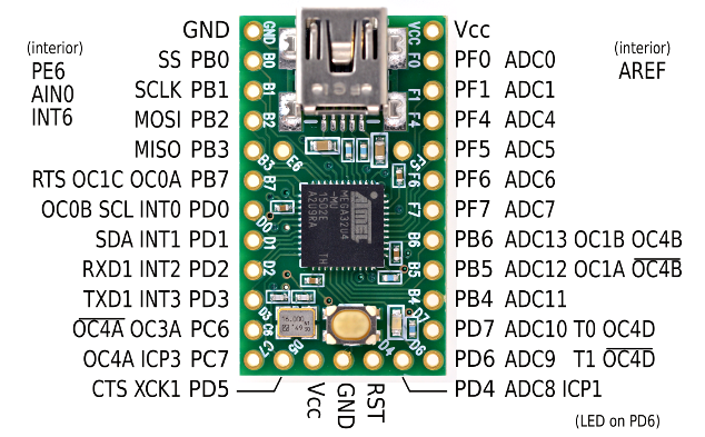
Teensy 2.0 has 25 IO pins.
You could wire them up in a more effective or compact manner, using less IO pins, but this should work.
Remember to not wire anything up to the power gnd and rst pins on the end of the teensy, and I recommend avoiding PD6 as it's the LED pin it sometimes has a problem.
Personally I'd wire it up a little differently but that's purely an aesthetic choice.


