Author Topic: Repairing Realforce PCB - UPDATE: SUCCESS  (Read 12929 times)

0 Members and 1 Guest are viewing this topic.

Offline nmur

  • ಠ_ಠ
  • Thread Starter
  • Posts: 1539
  • Location: Sydney
Repairing Realforce PCB - UPDATE: SUCCESS
« on: Wed, 23 May 2018, 09:45:47 »
hey all!

recently picked up an 86U from Yahoo JP, and the condition wasn't exactly how i had hoped. i've cleaned up the caps and case, sanded and painted the rusty switch plate, however i haven't been able to fix the Backspace, F12, PrtSc, and Pause key, which do not register. looking at the PCB, there was some residue around the area, suggesting a possible spill (though the other side looks great). i cleaned the area with 100% IPA, but it didn't change the result.

red dots indicate bad keys

front, before clean
196163-0

after clean
196165-1

back
196167-2

my suspicion is that the through-hole pads marked with purple in the 2nd photo have deteriorated, causing the circuit to fail. after looking at this sort of repair job, my plan would be to very carefully (this **** is tiny  :( ) scrape away the connecting trace shield layer on each side of the suspect holes to reveal the bare copper underneath. from there, i'd need to thread a new wire through the holes to connect each side of the PCB, then solder both sides up

this will be a tricky procedure, so i'd love to know before i go in if i'm on the right track here
« Last Edit: Fri, 25 May 2018, 11:53:49 by nmur »

Offline pixelpusher

  • * Elevated Elder
  • Posts: 4179
  • Location: Tennessee - USA
Re: Repairing Realforce PCB
« Reply #1 on: Wed, 23 May 2018, 10:28:14 »
seems like the right course of action.  I traced 3 of the 4 (can't tell without a full board shot for the 15 connection) to the same line.  The one centered under 123- It's probably just that one.  I've only ever had to fix a scratched trace before and it was pretty easy... everything just on one side of the board.  I'm not sure how to approach a through-hole issue other than what you have proposed.
« Last Edit: Wed, 23 May 2018, 10:30:29 by pixelpusher »

Offline nmur

  • ಠ_ಠ
  • Thread Starter
  • Posts: 1539
  • Location: Sydney
Re: Repairing Realforce PCB
« Reply #2 on: Wed, 23 May 2018, 11:19:42 »
seems like the right course of action.  I traced 3 of the 4 (can't tell without a full board shot for the 15 connection) to the same line.  The one centered under 123- It's probably just that one.  I've only ever had to fix a scratched trace before and it was pretty easy... everything just on one side of the board.  I'm not sure how to approach a through-hole issue other than what you have proposed.

yeah that one under 123 was really caked up before i cleaned it off. hoping that it's the only one i have to do

Offline xack

  • Posts: 50
    • Make'n'Modify
Re: Repairing Realforce PCB
« Reply #3 on: Wed, 23 May 2018, 13:23:06 »
yep, I think i would do the same, but you might use a multimeter and do a continuity test first to see if there is really no connection

Offline crtexcnndrm99

  • Posts: 341
  • Location: Brisbane, Australia
  • *profile image used without permission* ;)
Re: Repairing Realforce PCB
« Reply #4 on: Wed, 23 May 2018, 15:57:19 »
Dealing with the same issue with a similarly non-functioning 86u as well. It appears we have the same keys not working, except I also don’t have 6,8,9 keys functioning.

I’ve purchased some resistor, so the plan so far (with a little assistance) is to replace the resistors that I’ve traced this nonfunctioning row of keys back to.

Let me know how you go - it’d be great to hear what you’ve found :D
You're a smooth smoothie, you know? ~ Gaear Grimsrud

Offline nmur

  • ಠ_ಠ
  • Thread Starter
  • Posts: 1539
  • Location: Sydney
Re: Repairing Realforce PCB
« Reply #5 on: Thu, 24 May 2018, 08:39:44 »
best photo i could take of the holes. looks like the pads are gone completely from at least one of them, the others don't look so good

196265-0

Offline crtexcnndrm99

  • Posts: 341
  • Location: Brisbane, Australia
  • *profile image used without permission* ;)
Re: Repairing Realforce PCB
« Reply #6 on: Thu, 24 May 2018, 16:30:11 »
best photo i could take of the holes. looks like the pads are gone completely from at least one of them, the others don't look so good

(Attachment Link)
Oh that doesn’t look good. I’ll get some pictures for comparison up in a few days if I can.

I think we may have different issues though, I’ve had a few good looks over the front and back of the PCB and couldn’t see any abnormalities..
You're a smooth smoothie, you know? ~ Gaear Grimsrud

Offline Tactile

  • Posts: 1433
  • Location: Portland, OR
Re: Repairing Realforce PCB
« Reply #7 on: Thu, 24 May 2018, 16:48:04 »
I don't think you need wire. Those holes are so small you should be able to scrape and prep this side for a good connection, do the same to the other side and just solder. The hole should fill with solder almost without trying.
REΛLFORCE

Offline nmur

  • ಠ_ಠ
  • Thread Starter
  • Posts: 1539
  • Location: Sydney
Re: Repairing Realforce PCB
« Reply #8 on: Thu, 24 May 2018, 21:16:58 »
I don't think you need wire. Those holes are so small you should be able to scrape and prep this side for a good connection, do the same to the other side and just solder. The hole should fill with solder almost without trying.

interesting. do you think it would be easier to solder with a wire sticking out though?

Offline Tactile

  • Posts: 1433
  • Location: Portland, OR
Re: Repairing Realforce PCB
« Reply #9 on: Thu, 24 May 2018, 21:47:37 »
I don't think you need wire. Those holes are so small you should be able to scrape and prep this side for a good connection, do the same to the other side and just solder. The hole should fill with solder almost without trying.

interesting. do you think it would be easier to solder with a wire sticking out though?

I think easier without just because it eliminates one thing to be properly heated (the wire).
REΛLFORCE

Offline nmur

  • ಠ_ಠ
  • Thread Starter
  • Posts: 1539
  • Location: Sydney
Re: Repairing Realforce PCB
« Reply #10 on: Thu, 24 May 2018, 22:05:12 »
I don't think you need wire. Those holes are so small you should be able to scrape and prep this side for a good connection, do the same to the other side and just solder. The hole should fill with solder almost without trying.

interesting. do you think it would be easier to solder with a wire sticking out though?

I think easier without just because it eliminates one thing to be properly heated (the wire).
good point

there should be copper lining the inside of the hole right? that might be corroded too

not much of an issue though, if it doesn't seep through to the other side then I'll just heat the solder and poke a wire through

Sent from my ONEPLUS A5000 using Tapatalk


Offline nmur

  • ಠ_ಠ
  • Thread Starter
  • Posts: 1539
  • Location: Sydney
Re: Repairing Realforce PCB
« Reply #11 on: Fri, 25 May 2018, 11:53:29 »
update: SUCCESS

extremely painful process due to how ****ing small these things were, but we got there.

i know these photos make it look like i did a garbage job, but please try to keep the scale in mind (look at the size of the switch circles) and that i only had a chisel tip on me to work with

after confirming with a multimeter which pads i had to fix up (2), i  scraped away the adjacent trace shield layers, and because of how corroded the pads/traces were, i clipped some sip sockets for their wires which were a snug fit

196351-0

after fixing the first hole relatively easily (still hard as balls), i had a lot of trouble with the worse of the two. just couldn't get the solder to grab the traces next to it, the copper was just corroded away/scraped off by me mistakenly. so i ran a trace to the next through-hole that was fortunately not too far away
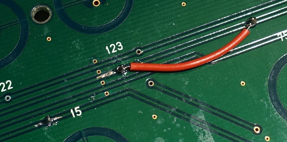
196353-1

i confirmed each of the broken keys with the multimeter, then with a dome/spring, then a full keyboard test

196355-2

extremely pleased that i managed to repair this thing, as i was dying to have an 86U for my WKL norbaforce. only thing left for me to do is to fix the lubing situation - thick krytox alone was too thick it seems

thanks for everyone's help in the thread!

Offline suicidal_orange

  • * Global Moderator
  • Posts: 4771
  • Location: England
Re: Repairing Realforce PCB
« Reply #12 on: Fri, 25 May 2018, 12:50:45 »
Looks pretty clean to me, good work keeping it out of landfill :thumb:
120/100g linear Zealio R1  
GMK Hyperfuse
'Split everything' perfection  
MX Clear
SA Hack'd by Geeks     
EasyAVR mod

Offline crtexcnndrm99

  • Posts: 341
  • Location: Brisbane, Australia
  • *profile image used without permission* ;)
Re: Repairing Realforce PCB - UPDATE: SUCCESS
« Reply #13 on: Sat, 26 May 2018, 05:45:12 »
update: SUCCESS

extremely painful process due to how ****ing small these things were, but we got there.

i know these photos make it look like i did a garbage job, but please try to keep the scale in mind (look at the size of the switch circles) and that i only had a chisel tip on me to work with

after confirming with a multimeter which pads i had to fix up (2), i  scraped away the adjacent trace shield layers, and because of how corroded the pads/traces were, i clipped some sip sockets for their wires which were a snug fit

(Attachment Link)

after fixing the first hole relatively easily (still hard as balls), i had a lot of trouble with the worse of the two. just couldn't get the solder to grab the traces next to it, the copper was just corroded away/scraped off by me mistakenly. so i ran a trace to the next through-hole that was fortunately not too far away

(Attachment Link)

i confirmed each of the broken keys with the multimeter, then with a dome/spring, then a full keyboard test

(Attachment Link)

extremely pleased that i managed to repair this thing, as i was dying to have an 86U for my WKL norbaforce. only thing left for me to do is to fix the lubing situation - thick krytox alone was too thick it seems

thanks for everyone's help in the thread!
Nice one!
You're a smooth smoothie, you know? ~ Gaear Grimsrud

Offline Lansky

  • Posts: 350
  • Location: Denmark
  • Realest motherthocker
Re: Repairing Realforce PCB - UPDATE: SUCCESS
« Reply #14 on: Sat, 26 May 2018, 05:51:29 »
Sweet, nicely done!
Norbaforce (88UB, BKE Heavy, silenced), Noxary XRF (stock 87UB, 55g) Singa R2 (retooled MX Blacks w/ 68g catweewee springs), LZ GH V2 (V1 Zealios 67g), RAMA U80-A (Holy GSUS)

Offline crtexcnndrm99

  • Posts: 341
  • Location: Brisbane, Australia
  • *profile image used without permission* ;)
Re: Repairing Realforce PCB - UPDATE: SUCCESS
« Reply #15 on: Tue, 26 June 2018, 03:02:29 »
Just realised I may have the same problem with a pad on my 86u (where the 7,9,+,-, insert, page up don't work), upon finding this missing (?) pad:
198691-0
You're a smooth smoothie, you know? ~ Gaear Grimsrud

Offline nmur

  • ಠ_ಠ
  • Thread Starter
  • Posts: 1539
  • Location: Sydney
Re: Repairing Realforce PCB - UPDATE: SUCCESS
« Reply #16 on: Tue, 26 June 2018, 03:27:32 »
Just realised I may have the same problem with a pad on my 86u (where the 7,9,+,-, insert, page up don't work), upon finding this missing (?) pad:
(Attachment Link)
yeah, looks similar

if you have a multimeter, it's super helpful at identifying which traces/pads need to be repaired

of you don't have one, you can get them for less than $10 shipped from Chinese stores

Offline crtexcnndrm99

  • Posts: 341
  • Location: Brisbane, Australia
  • *profile image used without permission* ;)
Re: Repairing Realforce PCB - UPDATE: SUCCESS
« Reply #17 on: Tue, 26 June 2018, 03:42:49 »
Just realised I may have the same problem with a pad on my 86u (where the 7,9,+,-, insert, page up don't work), upon finding this missing (?) pad:
(Attachment Link)
yeah, looks similar

if you have a multimeter, it's super helpful at identifying which traces/pads need to be repaired

of you don't have one, you can get them for less than $10 shipped from Chinese stores
cheers, i think i have one lying around.

would you mind telling me where/how you measured with the multimeter? I draw a blank when it comes to PCB's
You're a smooth smoothie, you know? ~ Gaear Grimsrud

Offline nmur

  • ಠ_ಠ
  • Thread Starter
  • Posts: 1539
  • Location: Sydney
Re: Repairing Realforce PCB - UPDATE: SUCCESS
« Reply #18 on: Tue, 26 June 2018, 08:10:06 »
Just realised I may have the same problem with a pad on my 86u (where the 7,9,+,-, insert, page up don't work), upon finding this missing (?) pad:
(Attachment Link)
yeah, looks similar

if you have a multimeter, it's super helpful at identifying which traces/pads need to be repaired

of you don't have one, you can get them for less than $10 shipped from Chinese stores
cheers, i think i have one lying around.

would you mind telling me where/how you measured with the multimeter? I draw a blank when it comes to PCB's

it's a little difficult to explain over the internet, especially the realforce pcb which is double-sided

essentially, those long horizontal traces connect the through-hole pads along its path. eg, look at the trace (pink line) connecting 3 through-holes (pink circles). if you stick your multimeter in any 2 of the 3 holes, you should get a completed circuit. if you don't, you have a bad pad.

198695-0

Offline crtexcnndrm99

  • Posts: 341
  • Location: Brisbane, Australia
  • *profile image used without permission* ;)
Re: Repairing Realforce PCB - UPDATE: SUCCESS
« Reply #19 on: Tue, 26 June 2018, 17:44:21 »
Just realised I may have the same problem with a pad on my 86u (where the 7,9,+,-, insert, page up don't work), upon finding this missing (?) pad:
(Attachment Link)
yeah, looks similar

if you have a multimeter, it's super helpful at identifying which traces/pads need to be repaired

of you don't have one, you can get them for less than $10 shipped from Chinese stores
cheers, i think i have one lying around.

would you mind telling me where/how you measured with the multimeter? I draw a blank when it comes to PCB's

it's a little difficult to explain over the internet, especially the realforce pcb which is double-sided

essentially, those long horizontal traces connect the through-hole pads along its path. eg, look at the trace (pink line) connecting 3 through-holes (pink circles). if you stick your multimeter in any 2 of the 3 holes, you should get a completed circuit. if you don't, you have a bad pad.

(Attachment Link)

I see what you mean now. I'm actually wondering whether a fix like your's to the pads has already been done on this 86u... two of the holes in the pic i linked have been filled with presumably wire already?
You're a smooth smoothie, you know? ~ Gaear Grimsrud

Offline nmur

  • ಠ_ಠ
  • Thread Starter
  • Posts: 1539
  • Location: Sydney
Re: Repairing Realforce PCB - UPDATE: SUCCESS
« Reply #20 on: Tue, 26 June 2018, 17:58:53 »
Just realised I may have the same problem with a pad on my 86u (where the 7,9,+,-, insert, page up don't work), upon finding this missing (?) pad:
(Attachment Link)
yeah, looks similar

if you have a multimeter, it's super helpful at identifying which traces/pads need to be repaired

of you don't have one, you can get them for less than $10 shipped from Chinese stores
cheers, i think i have one lying around.

would you mind telling me where/how you measured with the multimeter? I draw a blank when it comes to PCB's

it's a little difficult to explain over the internet, especially the realforce pcb which is double-sided

essentially, those long horizontal traces connect the through-hole pads along its path. eg, look at the trace (pink line) connecting 3 through-holes (pink circles). if you stick your multimeter in any 2 of the 3 holes, you should get a completed circuit. if you don't, you have a bad pad.

(Attachment Link)

I see what you mean now. I'm actually wondering whether a fix like your's to the pads has already been done on this 86u... two of the holes in the pic i linked have been filled with presumably wire already?
I think I recall a couple of the real tiny holes having solder on them? they looked like clean solder jobs too

sorry, my board is assembled right now so I can't see the pcb

Offline crtexcnndrm99

  • Posts: 341
  • Location: Brisbane, Australia
  • *profile image used without permission* ;)
Re: Repairing Realforce PCB - UPDATE: SUCCESS
« Reply #21 on: Tue, 26 June 2018, 18:07:24 »
Just realised I may have the same problem with a pad on my 86u (where the 7,9,+,-, insert, page up don't work), upon finding this missing (?) pad:
(Attachment Link)
yeah, looks similar

if you have a multimeter, it's super helpful at identifying which traces/pads need to be repaired

of you don't have one, you can get them for less than $10 shipped from Chinese stores
cheers, i think i have one lying around.

would you mind telling me where/how you measured with the multimeter? I draw a blank when it comes to PCB's

it's a little difficult to explain over the internet, especially the realforce pcb which is double-sided

essentially, those long horizontal traces connect the through-hole pads along its path. eg, look at the trace (pink line) connecting 3 through-holes (pink circles). if you stick your multimeter in any 2 of the 3 holes, you should get a completed circuit. if you don't, you have a bad pad.

(Attachment Link)

I see what you mean now. I'm actually wondering whether a fix like your's to the pads has already been done on this 86u... two of the holes in the pic i linked have been filled with presumably wire already?
I think I recall a couple of the real tiny holes having solder on them? they looked like clean solder jobs too

sorry, my board is assembled right now so I can't see the pcb
All good man, I don't want you to take it apart at all :thumb:

Oh ok, they must be factory soldered holes for some reason, they are very clean solder jobs as you said
You're a smooth smoothie, you know? ~ Gaear Grimsrud

Offline crtexcnndrm99

  • Posts: 341
  • Location: Brisbane, Australia
  • *profile image used without permission* ;)
Re: Repairing Realforce PCB - UPDATE: SUCCESS
« Reply #22 on: Fri, 23 November 2018, 20:25:32 »
Just realised I may have the same problem with a pad on my 86u (where the 7,9,+,-, insert, page up don't work), upon finding this missing (?) pad:
(Attachment Link)
yeah, looks similar

if you have a multimeter, it's super helpful at identifying which traces/pads need to be repaired

of you don't have one, you can get them for less than $10 shipped from Chinese stores
cheers, i think i have one lying around.

would you mind telling me where/how you measured with the multimeter? I draw a blank when it comes to PCB's

it's a little difficult to explain over the internet, especially the realforce pcb which is double-sided

essentially, those long horizontal traces connect the through-hole pads along its path. eg, look at the trace (pink line) connecting 3 through-holes (pink circles). if you stick your multimeter in any 2 of the 3 holes, you should get a completed circuit. if you don't, you have a bad pad.

(Attachment Link)

I see what you mean now. I'm actually wondering whether a fix like your's to the pads has already been done on this 86u... two of the holes in the pic i linked have been filled with presumably wire already?
I think I recall a couple of the real tiny holes having solder on them? they looked like clean solder jobs too

sorry, my board is assembled right now so I can't see the pcb

After several months, looking to revisit this saturday project.. how did you get the solder to go through and stick to the hole without the gold-coloured pad? I managed to stick a (spring) wire through the hole, but the multimeter either side of the broken hole still doesn't pick anything up.
You're a smooth smoothie, you know? ~ Gaear Grimsrud

Offline nmur

  • ಠ_ಠ
  • Thread Starter
  • Posts: 1539
  • Location: Sydney
Re: Repairing Realforce PCB - UPDATE: SUCCESS
« Reply #23 on: Fri, 23 November 2018, 22:08:26 »
Just realised I may have the same problem with a pad on my 86u (where the 7,9,+,-, insert, page up don't work), upon finding this missing (?) pad:
(Attachment Link)
yeah, looks similar

if you have a multimeter, it's super helpful at identifying which traces/pads need to be repaired

of you don't have one, you can get them for less than $10 shipped from Chinese stores
cheers, i think i have one lying around.

would you mind telling me where/how you measured with the multimeter? I draw a blank when it comes to PCB's

it's a little difficult to explain over the internet, especially the realforce pcb which is double-sided

essentially, those long horizontal traces connect the through-hole pads along its path. eg, look at the trace (pink line) connecting 3 through-holes (pink circles). if you stick your multimeter in any 2 of the 3 holes, you should get a completed circuit. if you don't, you have a bad pad.

(Attachment Link)

I see what you mean now. I'm actually wondering whether a fix like your's to the pads has already been done on this 86u... two of the holes in the pic i linked have been filled with presumably wire already?
I think I recall a couple of the real tiny holes having solder on them? they looked like clean solder jobs too

sorry, my board is assembled right now so I can't see the pcb

After several months, looking to revisit this saturday project.. how did you get the solder to go through and stick to the hole without the gold-coloured pad? I managed to stick a (spring) wire through the hole, but the multimeter either side of the broken hole still doesn't pick anything up.

on either side of the hole, i scraped away the top of the trace shielding. see the photo below, how i revealed the bare copper trace:


that means that when you go to solder the wire there, the solder grabs the wire and the trace on either side too.


Offline crtexcnndrm99

  • Posts: 341
  • Location: Brisbane, Australia
  • *profile image used without permission* ;)
Re: Repairing Realforce PCB - UPDATE: SUCCESS
« Reply #24 on: Sat, 24 November 2018, 00:42:21 »
@nmur absolute legend. fixed and working for the first time since I've had her  :thumb:

207664-0

now I may have to reach out to solve a unique keycap problem... (came without keycaps - currently a mash-up of Pro 1 and 108 caps)
« Last Edit: Sat, 24 November 2018, 00:47:58 by crtexcnndrm99 »
You're a smooth smoothie, you know? ~ Gaear Grimsrud

Offline nmur

  • ಠ_ಠ
  • Thread Starter
  • Posts: 1539
  • Location: Sydney
Re: Repairing Realforce PCB - UPDATE: SUCCESS
« Reply #25 on: Sat, 24 November 2018, 03:13:26 »
@nmur absolute legend. fixed and working for the first time since I've had her  :thumb:

(Attachment Link)

now I may have to reach out to solve a unique keycap problem... (came without keycaps - currently a mash-up of Pro 1 and 108 caps)
hell yeah dude, nice job!

the 7u space bar might be difficult to replace if you're looking for an oem one, but kbdfans are/were selling a pbt one. they might still have some on their site or aliexpress

Offline crtexcnndrm99

  • Posts: 341
  • Location: Brisbane, Australia
  • *profile image used without permission* ;)
Re: Repairing Realforce PCB - UPDATE: SUCCESS
« Reply #26 on: Sat, 24 November 2018, 06:04:14 »
Couldn't have done it without your thread - that makes two saved :P

Cheers, will probs have to go that way for the 7u spacebar, thinking a RF 10th AE set or coloured set for the other mods hmm...
You're a smooth smoothie, you know? ~ Gaear Grimsrud