Forgot to link this thread of interest. This way anyone reading this thread will also read the thread I link here and info will be in teh same place.
https://geekhack.org/index.php?topic=48950.0from that topic, here's what soarer has to say:
^from kbdbabel. Pin names (D5, D6) are general names for data pins not teensy pin assignments)
Here's xavierblak's controlelr photo. Note his is missing the adapter card board with the vreg on it

aha! it matches the mant library pic of it:
so now we know what all those chips are.
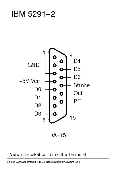
Here's the pinout from the hardware manual:
D1 1 20 Ground
(missing pin) -Strobe
D2 Ground
D3 D0
(unused) (unused)
(unused) (unused)
(unused) Frame Ground
D4 +5V
D5 Ground
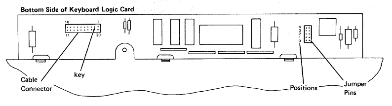
D6 10 11 OutputHere's a better description of the connector. Note how this compares with the kbdbabel image of the cable pinout.
I don't see specifically what pins go where but 5v goes to 5v or Vcc. GND goes to the GND pin on the teensy. All the other pins go to data pins on the teensy. You can actually see which ones by looking at his picture:

^soarer's 5291 wired up and ready to go. You can see 5v (red) and GND (black) plugged in at the proper locations 13 and 12e GND to co to any of the GND pins which are 12 20 and 18.
Also if you get random capacitance errors you might need to make sure the frame is connected to "frame ground. If you can tap into the USB cable's shield (usually it's tied to ground at the cable end unless you have made your own) then this should be connected to frame ground as well (Pretty sure).
Looking at the controller config file also tells a similar story:
scanrate 1
	debounce 1
	blocking 0
	muxstrobe_port PB6:0
	sense_delay 1
	muxstrobe_gate -PD1
	sense_polarity 1

	sense PD0
If I were you, I'd look hard at the image of him wiring it up to a teensy, and follow those pins and write a table of pin # on connector, pin name on teensy and pin assignment from the chart in the maint. manual and pin assignment from kbdbabel link.
Then see if you understand what's going on with the controller.
(basically it looks to me like a 1*83 matrix that exists as the output of several muxstrobe chips The location in the list of the muxstrobes is related to the key's position in the matrix. This is the sort of thing that I still don't understand *too* well.)
On teh plus side since there is no controller for the KB it's a LOT easier to convert to USB with soarer's code there. It also becomes easy to "overclock" the KB. Soarer said it supported fully a scanrate of 1000Hz, about what a cherry KB does now, and IIRC much faster than most IBM KB controllers (which were something like 14 us scan time).


