Hello all. I have recently acquired, for free no less, a Model M that was about to be thrown out at a grade school. It is a Lexmark 82G2383 that looked to be in good condition and I thought that I could possibly make it work for my own use.
I looked at many different websites and decided to make use of a "Blue Cube" PS/2 to USB adapter and use it to replace the original PS/2 cord which was frayed beyond use.
I thought I could simply follow the directions that were posted here:
http://zevv.nl/play/misc/ibm-usb/ but found that my PCB was of a different type than the one shown.
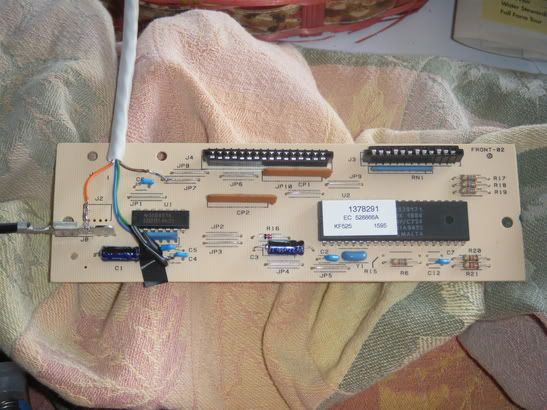 Board after starting the mod.
After some measurements I found that I would not be able to mount the adapter within the case like the site mentioned. So I came up with my own plan. By using four of the 8 wires within a CAT5, I could have a pigtail like connector sticking out the rear of the keyboard. It would be a bit awkward but it should work as long as the keyboard doesn't move around much.
I started by removing the connector for the original cable. I then tried to solder the four chosen wires, the solid ones to be exact, into the holes left behind by the connector. This did not work well do to the old contacts lifting off of the PCB. After removing the failed attempt I got around to following the traces and soldered the wires to points on the top of the board where they would, at least electrically, be on the same trace.
I then worked on removing the PS/2 connector from the blue cube and was about to solder on the wires when I realized that I had no idea what wire was for what portion of the PS/2 connection. I started following the traces again and quickly discovered the VCC and GND wires. I then had only two left. They both lead into, what I believe to be, the PS/2 interface IC. However I have no idea which one is the
data and which is the
clock.
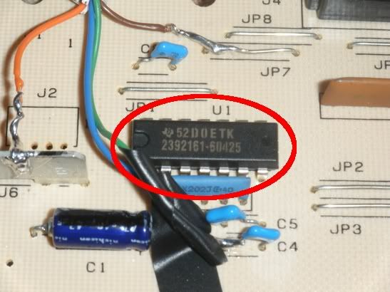 The IC in question.
I cannot find any information on this IC. I can tell you that the Brown wire is connected to pins 5 and 12, and the Green wire is connected to pins 2 and 3. Any help on which is the clock and which is the data would be very helpful.


