Author Topic: Switch on PCB does not work (Leeku 1800)  (Read 2286 times)

0 Members and 1 Guest are viewing this topic.

Offline madhias

  • Thread Starter
  • Posts: 1192
  • Location: Wien, Austria
  • BS TORPE
    • Madhias' Flickr
Switch on PCB does not work (Leeku 1800)
« on: Sat, 27 February 2016, 19:31:53 »
Recently I soldered switches and some LEDs to my shiny new Leeku 1800 PCB, and so far I got it working except the RETURN key of the numpad, and the LED of SCROLL LOCK (but that's not a big deal for now). When I had a problem with a switch in the past, mostly re-soldering the switch or the diode solved my problem.

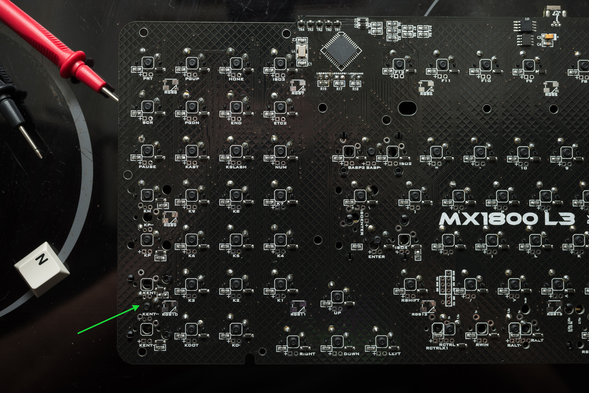
Today I bought a multimeter (yep, I had none), and tried to measure things I need for this problem - with the connectivity check. The faulty switch is connected to the bottom row, and the switch beeps to each switch in this row. Also when I search on the controller the connection of this row, it beeps (from the faulty switch to the controller pin).

My questions now are: what can or should I check with the multimeter? How could I 'just' make a wired connection from the faulty switch to a location I don't know? How do I measure the columns, and not the rows?

Here's a picture, I am not really good at soldering, but I am somewhat happy to have chosen this time a wire with small diameter. The really messy section is the LED of SCROLL LOCK, since I resoldered and soldered again for about 3 times... Argh.

« Last Edit: Sat, 27 February 2016, 19:40:00 by madhias »
... ...

Offline madhias

  • Thread Starter
  • Posts: 1192
  • Location: Wien, Austria
  • BS TORPE
    • Madhias' Flickr
Re: Switch on PCB does not work (Leeku 1800)
« Reply #1 on: Sun, 28 February 2016, 03:29:12 »
The SCROLL LOCK LED does work now, as I checked in Windows, since I updated the firmware now.

For the problem with the ENTER switch on the numpad, I think I will do a ghetto mod, since I am not that experienced with electronics. I did more testing with the multimeter, but to be honest I don't know at all what I can do - since the connections of the faulty switch to the controller seem to be OK. Maybe I am missing something!

What could go wrong with something like this:


I just solder a bridge from the faulty switch to the normal ENTER switch - I have two of them! Is it OK, to have two switches on one position?

But how to do best: should I leave everything as it is, and solder the bridge, or should I eliminate the diode only, or should completely isolate the pins of the switch from its current position? If someone can follow me now...
... ...

Offline suicidal_orange

  • * Global Moderator
  • Posts: 4771
  • Location: England
Re: Switch on PCB does not work (Leeku 1800)
« Reply #2 on: Sun, 28 February 2016, 18:47:45 »
You've checked one side is connected, now you need to find which diode it connects to on the other pin then the other end of that diode should be connected to the other end of the other diodes in the column.  The way the holes are laid out I would think both the pads you're using would be connected to the ones just above, but you say it's in the bottom row?  A pic from a slight angle might help see what's connected, but it looks to be on the other side of the PCB...

You could connect two switches to the same pads but you're right that you need to make sure that it's not connected in it's original position at all, otherwise it will activate the key below normal enter in the same column or the key above numpad enter as well as enter.  If the pins go straight down the middle of the holes they won't touch the sides and you should be fine.

Would look tidier if you could connect it to whichever of the 1u spaces above or below it should be connected to though - what happens when you touch a wire between the pads on both of them, do either register as keypresses?
120/100g linear Zealio R1  
GMK Hyperfuse
'Split everything' perfection  
MX Clear
SA Hack'd by Geeks     
EasyAVR mod

Offline madhias

  • Thread Starter
  • Posts: 1192
  • Location: Wien, Austria
  • BS TORPE
    • Madhias' Flickr
Re: Switch on PCB does not work (Leeku 1800)
« Reply #3 on: Mon, 29 February 2016, 05:40:17 »
You've checked one side is connected, now you need to find which diode it connects to on the other pin then the other end of that diode should be connected to the other end of the other diodes in the column.  The way the holes are laid out I would think both the pads you're using would be connected to the ones just above, but you say it's in the bottom row?  A pic from a slight angle might help see what's connected, but it looks to be on the other side of the PCB...

I have measured diode to diode now, and tried to find out which switches are connected. The numpad ENTER seems to be connected to two other switches above (one empty), the one below (empty) and then to the bottom row. The traces are not easy to follow with this black colored PCB!

Would look tidier if you could connect it to whichever of the 1u spaces above or below it should be connected to though - what happens when you touch a wire between the pads on both of them, do either register as keypresses?

Now that is a great idea! I have just handheld a bridge to the ENTER switch location below the one I am using, and it is registered. Since both of them are in the same row / column, it is no problem if I am correct? I think I will just do it like that, the easiest solution of all. A thousand thanks to you!
... ...

Offline madhias

  • Thread Starter
  • Posts: 1192
  • Location: Wien, Austria
  • BS TORPE
    • Madhias' Flickr
Re: Switch on PCB does not work (Leeku 1800)
« Reply #4 on: Mon, 29 February 2016, 06:54:28 »
In the end the solution was simple, but I learned a lot! And have a multimeter now. Thanks suicidal_orange again for your hint.

... ...