Disclaimer: sorry if i put this topic in wrong forum, move it to more convenient forum if it require.Hello forum. Currently i'm working on yet another ergonomic keyboard, which is not announced yet. And i need to draw a schematics for my circuit boards (4 circuit boards total). And here i require your help.
Everything else is just fine: i know well C programming language, i can use "tmk_keyboard", 3D model of my keyboard is prepared to be printed, etc. Except one this simple thing - electronics. In particular - PCB circuit scheme.
Sadly, this is my first project which require PCB, and at least basic knowledge of electronics. I ofc. know how electronics and mechanical keyboards work, but i have no experience of drawing PCBs.
I will use cherry ML switches, and AVR-USB162MU (or it's analogue) as a controller.
But i currently stuck on PCB drawing because i have no idea how to draw it.
Here is example of PCB of cherry ML based keyboard:

And here is example of scheme of approximately similar keyboard (sorry - scheme is transparent):
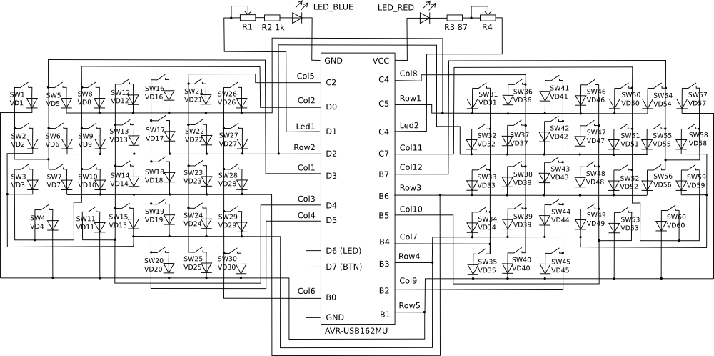
So here i require your help:
1) Do any of you know how i should connect switchers to controller? Especially cherry ML and AVR controllers.
2) What i should know before i attempt to draw nice scheme, and what i should do before that?
3) Is cherry MX similar to cherry ML? Can i use MX-based scheme to draw my own? (with modifications ofc.)
And yes, here is small picture of Cherry ML's pins:
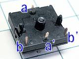
Hopefully this will help you help me.
I will tell a bit more about my keyboard in different topic, right after i'll assemble it, but here is basic layout of my keyboard:

That's why i need 4 PCBs to get it done. It's divided by 2 parts, and each part have "main frame" with all basic keys, and "thumb frame", with 4 thumb keys.


