This article is intended as a supplement to
DOX's design of a 63-key keyboard.
Together with multiple members from the community I've made some modifications, and also integrated to mounting of the teensy to the PCB layout and added support for LED backlighting.
The list of tools you will need:
- Soldering gun/station
- Solder/flux, and whatever else you need to solder stuff
- Wire cutter
- Tweezer
- Your two hands
As for material:
- PCB from http://expresspcb.com/ (here: there are 2 versions, 1 uses the regular shift, one uses a short one and gets an additional button)
- 62 Cherry MX switches
- 62 1N41418 switching diode
- Teensy from http://www.pjrc.com/store/teensy.html
- 62 LEDs of your choice (forward voltage must be <2.5v)
- 30 resisters calculate ohm for a chain of LED in series of 2's powered by a 5v supply source
- 4 resisters calculate ohm for single LED powered by a 5v supply source
- 4 cherry stabilizers (1 space bar, 3 smaller ones)
- 1 mini USB receptacle (digikey)
- 1 mini USB male connector (here)
- 4 small wires
- 2 12-pin spacer thing for the teensy (here)
- 1 low profile DIP 4 way switch (ebay)
Tips before we start:
a. Safety!! Keep all combustable stuff away from the soldering station, and be careful when working with it, getting burned by it really sucks
b. be patient! rushing will only cause screw-ups that will take more time to fix
c. double check EVERYTHING and test it whenever you can, this will cut down the time it takes to find problems later on and minimize mistakes.
Feel free to ask me anything if parts of the tute is confusing
1. Unwrap your PCB :P it'll make it real difficult to solder if you don't
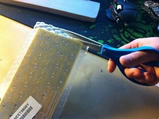
2. Trim off the sharp corners (Optional, do this only if you wish to use this board with a poker X case
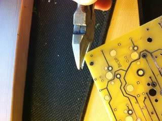
I also took a 600grit sand paper to round off the corners for a cleaner look
3. Solder the DIP switch, make sure it is placed on the back side (where you can read the words "DOXish")
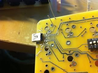
4. Solder the the USB receptacle to the upper right slot, make sure it is placed on the back side (where you can read the words "DOXish")
be sure to press it in firmly and make sure it is sitting flush against the PCB, if this is a bit off, it will not fit in the poker case.
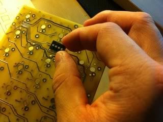
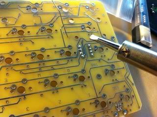
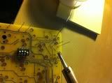
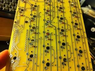
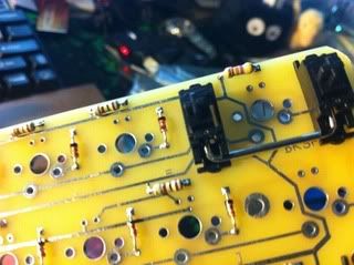
5. Next comes the tedious part, we are to solder each of the diodes to the board.
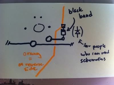
Due to wiring in a compact space, many of the diodes aren't pointed in the same direction, so here the best tip I can give you to figure out how to orient each one:
the black band on the diode should be pointing away from the slot where the cherry MX switch will be placed in.
and here's for our visual learners:
so solder... solder... solder...
....
...
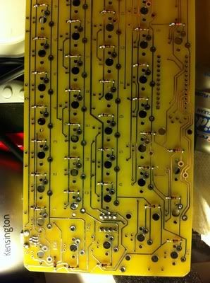
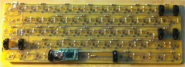
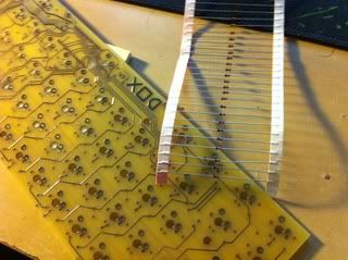
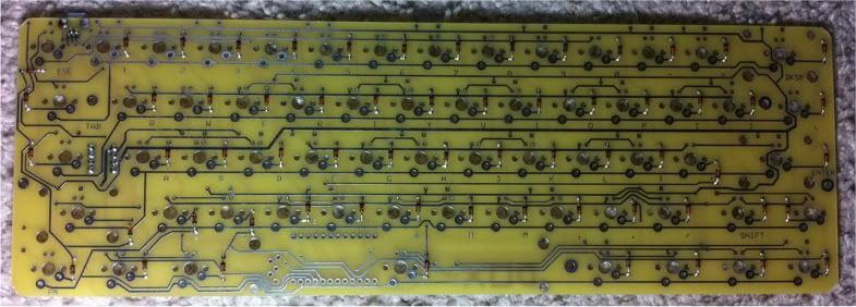
and this is what it should look like when all the diodes are soldered:
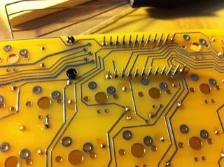
6. Solder the resisters, all of them should be the lower ohm ones (the ones I used are 100ohm, and they are for a 2.2v orange LED, its capable of 20mA but I've toned it down to 6mA because its still plenty bright, and saves me laptop some power.)
except for the following keys: (Space, Backspace, Esc, and F) these will need the higher ohm resister (im using 470ohm)
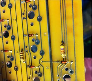
What I did as I went along to make sure everything is alright, I have 2 LED on next to me while I solder to make sure each resister soldered in place, I would stick the 2 LED in the associated slots and let gravity hold them down (hold the board perpendicular to the floor) to make sure it works.
7. If you haven't already I would go ahead and put the stabilizers in, this can happen anytime if you want really, I just like to have it set now because its easier to press them in.
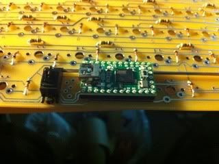
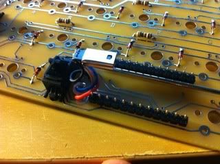
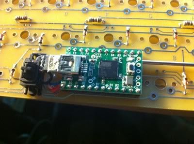
8. grab a 2 switches and put them on C and V, and place the spacer pins for the teensy in its slot, next slide the teensy, the switches should be holding the teensy at a certain height, hold it there, and turn the board around. Solder the pins. (i know I didn't do the switches in the picture, but it was easier with the switches as guides.
solder away...
 DO NOT SOLDER THE TEENSY DOWN YET!!! JUST THE SPACER/PINS
9. Now for the more difficult part, we are going to cut and solder wires onto the USB plug meant fo the teensy.
first: cut the metal casing of the usb plug and insert the plastic piece into the front half:
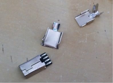
discard the back half, we wont be needing it.
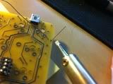
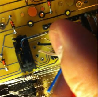
next ,cut 4 short pieces of wires, the thinner it is, the easier this is part is going to be, like this:
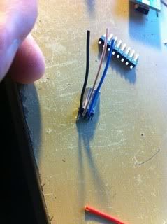
this may be easier if you have a clip or something to hold the usb down, but its doable without (I did :D)
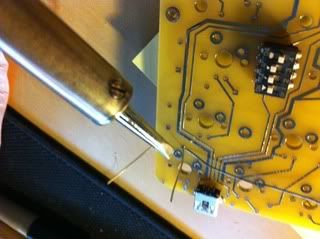
Soldering this will take some patience, you dont need the best soldering iron out there to do it, you've seen from the above photo, the tip of my soldering iron is almost as wide as half of the USB, but it's still doable.
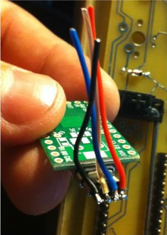
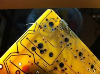
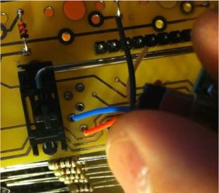
after that is done, take the wires between your fingers and twist, the holes on the PCB are oriented in the opposite position of the USB wires:
push the wires into the holes, and solder. There are only 4 wires, so the second hole (counting from the top) should be left open.
(please also note the the photos may not be in the same orientation as how your working on the pcb, look at the space bar stabilizer, and make sure you are oriented the right way)
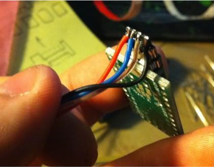
I'm showing the pictures 2 wires at a time, so hopefully it would be clear enough. I also purposely used 4 different colors, so you can refer to the above for which pin goes where:
solder
done...
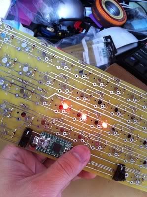
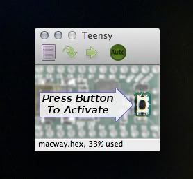
10. now plug in the Teensy to this usb (the switches on C and V will help hold it down) and plug what we got so far into the computer, start up the teensy loader and press the button ont to make sure that it's being read properly
When it is first plugged in, nothing really happens:
after the button is pressed: ---> double check, click the reboot and press the button again
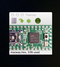

I've also took this chance to flash in the firmware.
good?
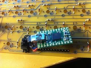
then go ahead and solder down the teensy:
if you're worried about loose connections, solder the USB plug onto the USB receptacle of the teensy like the picture above
(be careful to not leave the soldering iron there too long, you will melt the insides of the USB.
Take a piece of wire left from the resisters or diodes, and test out if the switches are working properly by shorting the 2 spot where the switch pins goes into.
11. now we wait for the cherry MX switches to arrive in the mail and I will continue writing this guide.
work in progress...