Author Topic: SAMPad - Sundstrand Adding Machine - Numpad that is usable on right & left side  (Read 39070 times)

0 Members and 1 Guest are viewing this topic.

Offline MOZ

  • KING OF THE NEWBIES
  • * Maker
  • Thread Starter
  • Posts: 3981
  • Location: Jo'burg
  • Busy making stuff
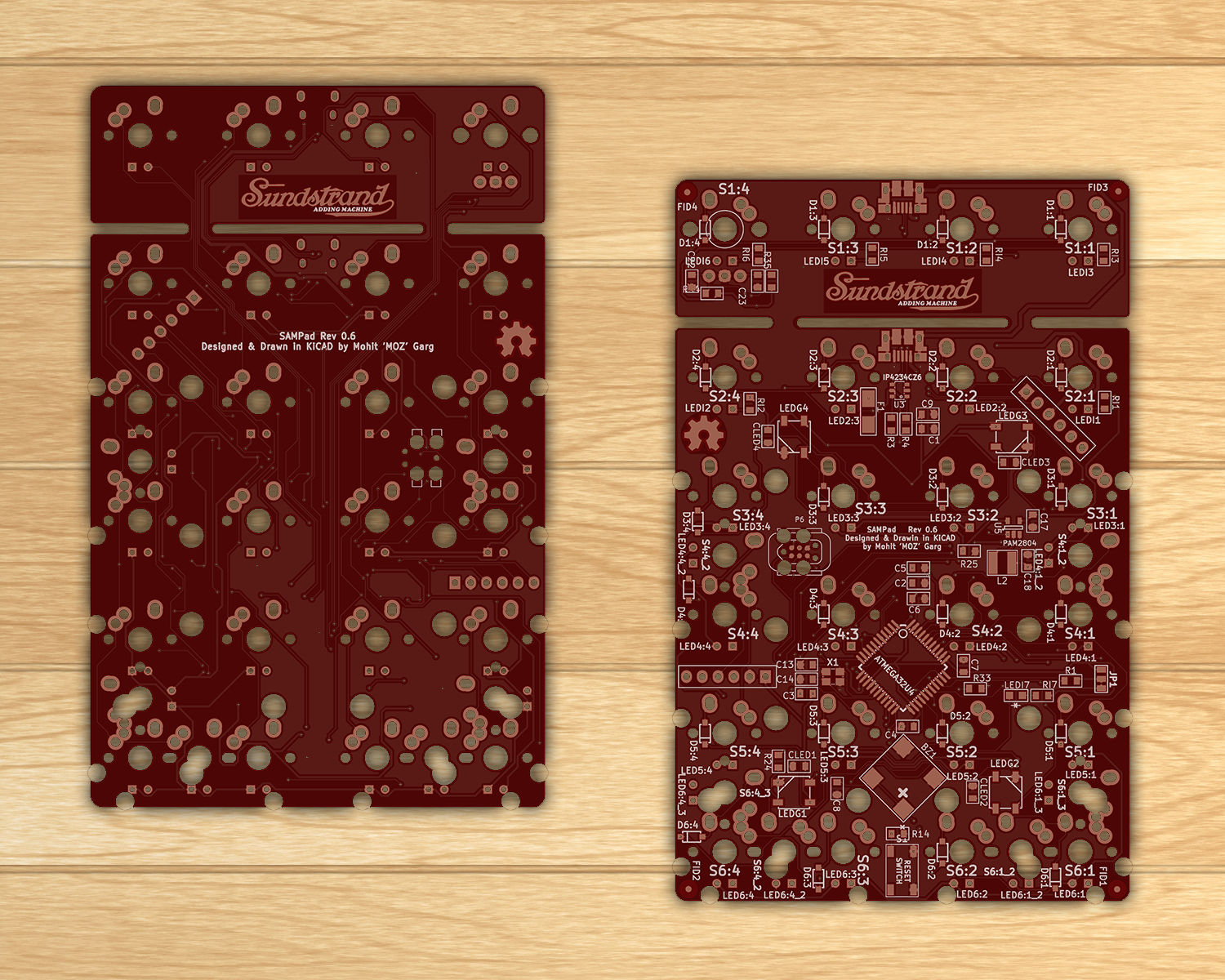
This is a custom numeric pad that is designed to be usable on the right side of the keyboard or on the left (With a mirrored layout if required). There is a gap in the top row and the second row of 1.25U. The top row can be broken off by simply scoring the two brifges and snapping. The bottom 5 rows can then be used in conjunction with a 60%/65% keyboard.

SAMPad stands for Sundstrand Adding Machine. David Sundstrand was the inventor of the 10-key adding machine, the layout of which is used till date on most numeric pads. This is a humble dedication to the great man.

Features:
-- Open Source Design
-- Fully Programmable Keys
-- Numpad can be mirrored for use on the left side of the main keyboard.
-- Multiple layers
-- Alps/Cherry (PCB/Plate) support
-- PCB mount stabs supported
-- Backlight, LED on bottom for windowed keycaps
-- 6 Indicator LEDs, 4 on the top row and one on either Num Lock positions (Regular and mirrored)
-- 4 SMD RGB LEDs on the bottom of the PCB for under/side glow
-- SMD (SOD-123) diodes only
-- Individual resistors for the LEDs not required as it uses a dedicated LED driver
-- Using large (0805) capacitors and resistors so it is easier to hand-solder
-- Possibility to add a buzzer
-- Possibility to add a rotary dial on the top-right most key position for changing volume, LED brightness, etc.
-- PCB compatible with Winkeyless.kr case

Layout options decided/implemented:
-- Standard numpad with extra row on top with a 1.25U vertical offset that matches most TKL boards.
-- Possibility for upto 5*4 + 4 keys layout
-- Mirrored numpad layout for use on left side of main keyboard


To Do (immediate):
-- Add RGB support to EasyAVR
-- Add rotary encoder support to EasyAVR
-- Add buzzer support to EasyAVR

GitHub Link:  https://github.com/mohitg11/SAMPad

Current PCB design::
« Last Edit: Mon, 02 May 2016, 15:17:18 by MOZ »

Offline MOZ

  • KING OF THE NEWBIES
  • * Maker
  • Thread Starter
  • Posts: 3981
  • Location: Jo'burg
  • Busy making stuff
This one was a ***** to trace, as you can see the back of the PCB is busy!

Offline SpAmRaY

  • NOT a Moderator
  • * Certified Spammer
  • Posts: 14667
  • Location: ¯\(°_o)/¯
  • because reasons.......
I'm not in the market to buy anything right now but this is really cool.

Offline zhihuichan

  • Posts: 136
  • Click,click,click
I really need this. To bulid a left hand Numpad !

Offline romevi

  • Formerly romevi
  • * Exalted Elder
  • Posts: 8941
  • Location: The Windy City
Great use of the left side.

Offline regack

  • Posts: 660
  • Location: Thessia
That's really nice MOZ, I like how everything routes through the two thin breakpoints for the top - neat and tidy there.

Offline ika

  • Posts: 668
  • Location: NE Ohio
I literally just bought a b.pad two days ago but this looks really cool, especially the rotary switch part. Interested to see how that turns out!

Offline Data

  • Posts: 2608
  • Location: Orlando, FL
This is awesome.  Some of the soldering looks intimidating.   :-X

Offline 0100010

  • Posts: 1127
  • Location: DFW, TX, US
  • Not Sure
Don't need one; but I want one.
  Quoting me causes a posting error that you need to ignore.

Offline TalkingTree

  • Posts: 2452
  • Location: Italy (142)
    • My projects
I dare to ask, is it possible to get a PCB without the gap between the first and second row? I was looking for that layout specifically.
Thanks in advance.
My opensource projects: GH80-3000, TOAD, XMMX. Classified: stuff

Offline MOZ

  • KING OF THE NEWBIES
  • * Maker
  • Thread Starter
  • Posts: 3981
  • Location: Jo'burg
  • Busy making stuff
I dare to ask, is it possible to get a PCB without the gap between the first and second row? I was looking for that layout specifically.
Thanks in advance.
It's not supported on this PCB, however it should be pretty trivial to edit the KiCAD file to not have the gap between the top two rows.

Offline TalkingTree

  • Posts: 2452
  • Location: Italy (142)
    • My projects
I dare to ask, is it possible to get a PCB without the gap between the first and second row? I was looking for that layout specifically.
Thanks in advance.
It's not supported on this PCB, however it should be pretty trivial to edit the KiCAD file to not have the gap between the top two rows.
Gotta give it a go. Thanks.
My opensource projects: GH80-3000, TOAD, XMMX. Classified: stuff

Offline MOZ

  • KING OF THE NEWBIES
  • * Maker
  • Thread Starter
  • Posts: 3981
  • Location: Jo'burg
  • Busy making stuff
Updated the PCB on GitHub. I feel it is now complete and will move onto designing the acrylic case and in parallel I've been working on adding support for RGB LEDs to Easy AVR.

Offline MOZ

  • KING OF THE NEWBIES
  • * Maker
  • Thread Starter
  • Posts: 3981
  • Location: Jo'burg
  • Busy making stuff
Working on a project at work, it struck me that I had complicated this and the TS65 project too much and had strayed away from the initial idea. I was also working on the cases for both of them over the weekend and realised the TS65 looked rather ugly with the extra bare space on the left side. The final straw was that I've been flooded with a lot of work IRL and I need a split design board to use for the long hours at work now that I've sold my Ergodox.

What this all means, is I'll be toning down both the project. For the SAMPad it only means removing the 3.3V regulator. For the TS65, I'll not be implementing wireless and rotary encoder (As there is no place for it). RGB LEDs, buzzer and trackpoint extension will stay.

Following this line of thought, I've updated the GitHub repo for SAMPad to Rev 0.4 with the changes implemented. I also pushed Rev 0.3 before I pushed 0.4, so it's up there for anyone to explore.

Offline MOZ

  • KING OF THE NEWBIES
  • * Maker
  • Thread Starter
  • Posts: 3981
  • Location: Jo'burg
  • Busy making stuff
Completed the case and uploaded it onto GitHub.

I've gone with a slightly different case to the ones I've done before. There is only one thick middle layer this time, a top/plate layer and a bottom layer along with a diffuser layer.

One would have to file the USB part that protrudes from the middle layer. Just cutting it would result in an unnecessarily large cavity, thus I've left it to the user to file to get the right height, it can easily be ammended in any vector software to be cut if required.

There is a diffuser layer that sites inside the middle layer and above the bottom layer. The purpose of this layer is to diffuse the RGB LEDs to the sides. It has cutouts for the thicker components.


I've also been working on the firmware side of things. I've added support for EasyAVR, so the basic keyboard should be usable with EasyAVR. I've got the UI for the RGB LED done as well as LEDs working with colors set via the firmware code. Now have to link the two.


Offline MOZ

  • KING OF THE NEWBIES
  • * Maker
  • Thread Starter
  • Posts: 3981
  • Location: Jo'burg
  • Busy making stuff
Corrected a minor issue on the PCB with the MCU UCAP connection. Comit pushed to GitHub

Offline help-14

  • Posts: 30
    • KeySekai
Just printed your PCB for testing, keep up the great work  :thumb:


Offline MOZ

  • KING OF THE NEWBIES
  • * Maker
  • Thread Starter
  • Posts: 3981
  • Location: Jo'burg
  • Busy making stuff
Wow. Looks like it came out good. Tell me, is the "Adding Machine' part readable?

Let me know when you build it, I'll be pushing the config file for Easy AVR soon, some features might not work right now. I'll see if I have time, I'll add QMK configuration as well, with that everything besides the rotary encoder should work.

I'm about to place an order for the PCB and parts myself this weekend, but it will be a while before they reach me and I can build them.

Offline MOZ

  • KING OF THE NEWBIES
  • * Maker
  • Thread Starter
  • Posts: 3981
  • Location: Jo'burg
  • Busy making stuff
BOM updated.

Offline punkpc

  • Posts: 136
  • Location: Naptown, Indiana
Looking forward to being able to get one of these. Can't wait!

Offline MOZ

  • KING OF THE NEWBIES
  • * Maker
  • Thread Starter
  • Posts: 3981
  • Location: Jo'burg
  • Busy making stuff
Updated to Rev 0.6. Changes,
-- Changed how the HWBE pin is pulled. Default is pull-down but you can cut the track and then have it pulled-up
-- Changed board outline so that corners are rounded for routing if panelized

I'm waiting for feedback from help-14 before placing an order for components and PCB.

Offline MOZ

  • KING OF THE NEWBIES
  • * Maker
  • Thread Starter
  • Posts: 3981
  • Location: Jo'burg
  • Busy making stuff
So, here's my first batch of PCBs from EasyEDA. I found the quality to be excellent along with the great service and splendid pricing.


Offline infiniti

  • I <3 KB
  • * Senior Moderator
  • Posts: 2405
  • Location: Thrilla, Manila, Philippines
  • Bob was here
    • PM me and ask for a custom title!
Great lookin' PCB, MOZ! :thumb:

Offline help-14

  • Posts: 30
    • KeySekai
Awesome, if it work then I'll order 10 more :))

Offline Data

  • Posts: 2608
  • Location: Orlando, FL
Nice.  Still looks super intimidating.   :-X

Offline MOZ

  • KING OF THE NEWBIES
  • * Maker
  • Thread Starter
  • Posts: 3981
  • Location: Jo'burg
  • Busy making stuff
Yeah the back side looks super busy

Offline MOZ

  • KING OF THE NEWBIES
  • * Maker
  • Thread Starter
  • Posts: 3981
  • Location: Jo'burg
  • Busy making stuff
Yeay, first test build was successful! Hot air soldering is so much faster!

I used Easy AVR to program the board, all keys registering, indicator LEDs working as they should. I haven't got my switches yet, so I just shorted the switch pins to test and it's working.

Also, I forgot the backlight LEDs are current controlled from the driver, so to test the LED I just put one in through the holes and it was BRIGHT! In two seconds it died, 200mA going through a single LED can't be good. THis was the 2x3x4mm LED off ebay, rated for 20mA

Will now try to program it using QMK, and test the audio and RGB LEDs (Still waiting to receive the RGB LEDs as well). Already discovered that to use the buzzer, I'll have to swap the buzzer pin (B4) with another pin (C6) as the Timer 3 is used for the buzzer in QMK. Oh well, will get to it soon.

Offline xtrafrood

  • formerly csmertx
  • * Elevated Elder
  • Posts: 2715
  • Location: Gainesville, FL
  • wildling
Bookmarking this page for updates. The PCB looks beautiful, can't wait to see a full build

Offline carzian

  • Posts: 7
  • Just a guy in a robot
Don't mean to revive a dead thread, but I was wondering if Moz has any updates?

Offline vim_commando

  • Posts: 52
  • Location: USA, Hawai'i
    • LaserCTRL
Don't mean to revive a dead thread, but I was wondering if Moz has any updates?

No, I think you meant to. :))

I'd like to know the status on this too, the PCB looks like something I need for a build I've got rattling around in my head.


Offline MOZ

  • KING OF THE NEWBIES
  • * Maker
  • Thread Starter
  • Posts: 3981
  • Location: Jo'burg
  • Busy making stuff
I did make a build with this, right before I was smashed in the face with the thing called life. Keyboard was working, so were back light LEDs and RGBs, didn't test the buzzer or encoder. Maybe in a month or so I can get back on the hobby train and give some more updates.