So...what the title says.

)
I figured I would write a walkthrough so that people would understand how to disassemble their plate mounted PCB keyboards. Keep in mind that this is not a hard process but a tedious one where small mistakes can be very costly. You will need to completely take off the cover and desolder each switch that you want to remove for lubrication or cleaning etc.
Anyways, to begin, you'll need these tools.
An old credit card
Philips head screw driver
Desoldering Iron
Soldering Iron
Solder
Begin by first powering off your keyboard. Just disconnect the thing. Afterwards, remove the three screws in the back. One of them will be covered by a warranty sticker, which you have to break and void your warranty to do this. Now, most warrantys are no longer than a year, so if you've had your keyboard for more than that, then it's not good anyway.
This being done, now remove the plastic cover. The top part comes off first, as the PCB is screwed into the bottom part. The plastic cover is held on by small tabs (4 on each long edge) that can be dislodged using the old credit card. This will be a slightly painful process, and be careful not to crack your cover. Some parts get thin.
Also, I wanted to note that where the three screws were screwed in the back, on the top cover there are protrusions so the screw can enter there. See picture. Because of this, you can't just pry off one side and then lift off the cover. You will break it. You have been warned.
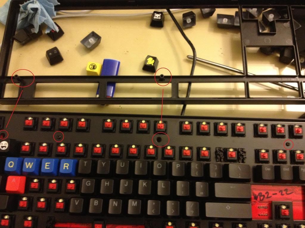
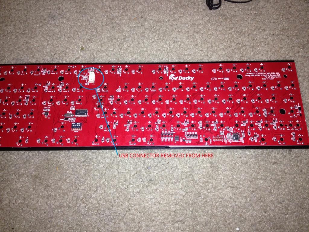
Now, with the cover off, it should look like the above picture. Do remove the two screws holding down the PCB, but don't rip it off yet! The mini-USB connection is linked via a connector on the back of your PCB. After you remove the two screws, gently lift off the PCB about an inch or so and disconnect the connector, which should be in the place shown in the next picture.
Now for me, the stupid ginger ale got into my X, C and left Alt keys. So you can see the switches removed here. Now, for a backlit keyboard, there are also little pins for the LED. Keep in mind that the LED stands for Light Emitting Diode. Why am I mentioning this? Because a diode is basically a one-way valve for electrical connections. That means that unlike a standard halogen bulb, an LED can only be oriented a certain way, or else it will not emit light. So do keep in mind how you remove your LED's as they need to be put in the exact same configuration. Luckily, if you look at the LED, there are clearly two sides. There is a smaller side and a larger side with the little cone on top where the light emits. Orient them the same way as your other switches to make sure they work. Also, this is when you can put in different LED for WASD, etc. Just dont desolder the switches, just desolder LED and add new ones. Voila!
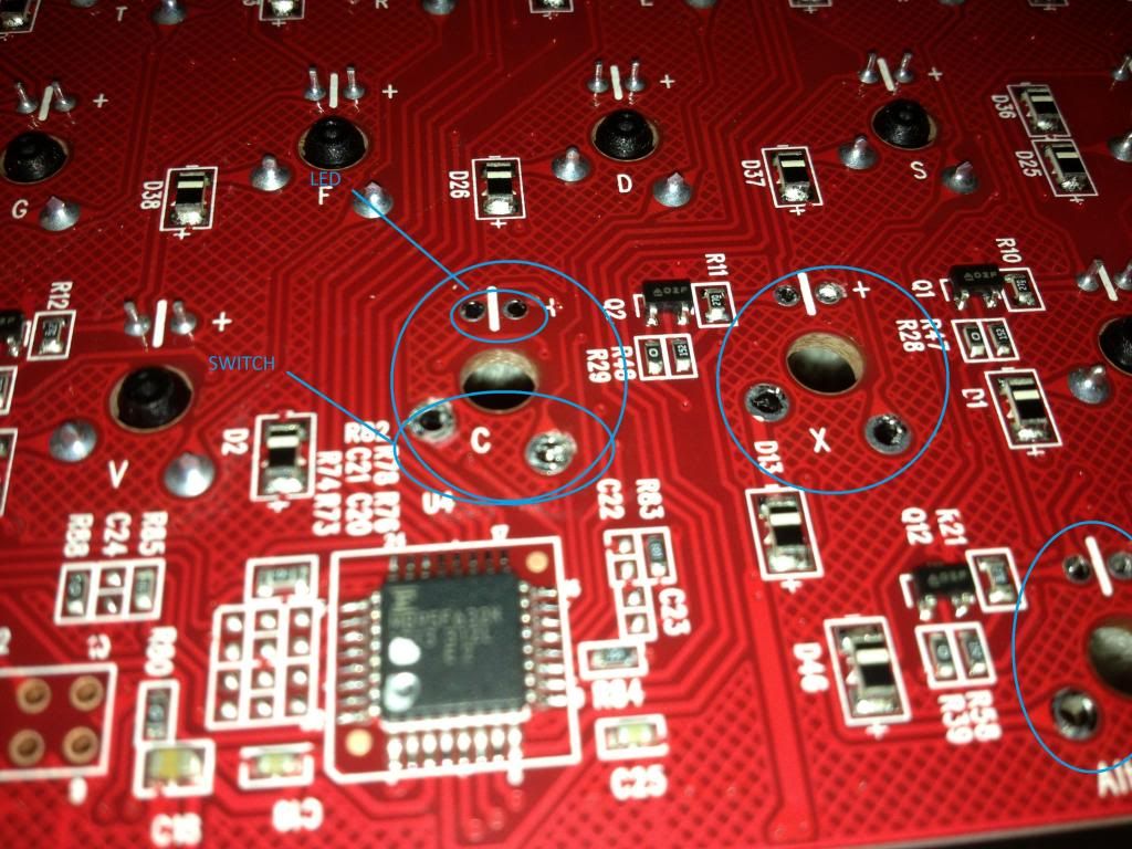
Where to desolder is listed above. You can tell the center of the switch by that little black circle that is the center of all the pins.
So, now you remove your switches after you desolder. Make sure you completely desoldered, to know this, you can move the pins around a little. After, remove your key, and push the top and bottom of the switch. This should pop it out. You can begin with the top, lift it, and then do the bottom and lift and it should pop out.
Afterward, there are 4 tabs that hold the top body from the bottom body. These are on the left and right. Apply pull on one side, undo those tabs, then keep a fingernail in and undo the other 2. This should open up the switch.
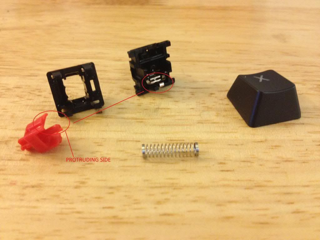
Notice that the plunger, has two sides. There is a side that protrudes more. This is to be put in with the protrusion facing the switch part. Feel free to disassemble the switch, and clean with mild soap and water. Make sure it is COMPLETELY dry. I like to use a duster and blast it, usually gets all water out in about 20 seconds. Don't worry about corrosion, the switch contacts are made of gold plated so it should be fine.
Make sure to build the switch back carefully, and check operation and orientation. There are two small holes in the front where the LED leads can fit through, make sure the top and bottom align.
Resolder switch back in, then resolder LED. Remember about the orientation.
Connect USB, rescrew 2 screws, install cover, reinstall 3 more screws. You are done! (this last part takes a bit longer than I made it sound)
There are some videos on youtube you can watch as well, or feel free to PM me on any questions. Easy project, now you can change out any switches and any LED!


